Flywheel pulse synchronous generator system with embedded permanent magnet rotor
A pulse synchronous, synchronous motor technology, applied to synchronous motors with static armatures and rotating magnets, to control the direction of generators, electrical components, etc. through magnetic field changes, can solve the problem of low energy density, low power density, large volume and weight, etc. problems, to achieve the effect of small size, high power density and energy density, and strong system overload capacity
- Summary
- Abstract
- Description
- Claims
- Application Information
AI Technical Summary
Problems solved by technology
Method used
Image

Examples
specific Embodiment approach 1
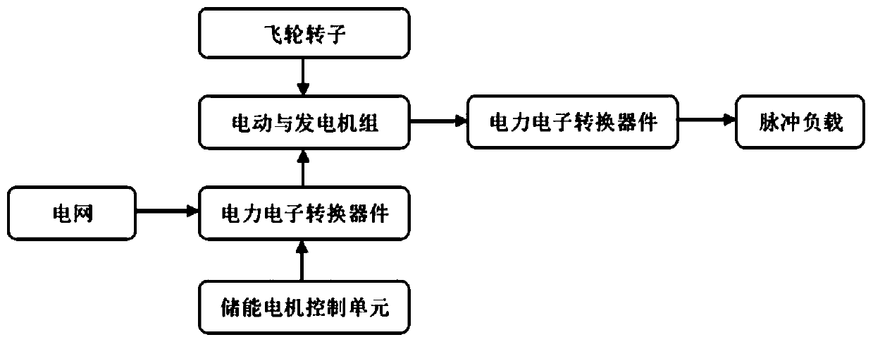
[0043] Specific embodiment one, the following combination Figure 2 ~ Figure 6 To illustrate this embodiment, the flywheel pulse synchronous generator system with embedded permanent magnet rotor in this embodiment is as figure 2 As shown, the system includes an input inverter, an input motor, an embedded permanent magnet rotor synchronous motor, an output rectifier, an excitation current adjustment unit, and an inertial flywheel. The output terminal of the input inverter is connected to the lead wire of the input motor; The output end of the armature winding of the permanent magnet rotor synchronous generator is connected to the AC input end of the output rectifier, the output end of the armature winding of the embedded permanent magnet rotor synchronous generator is connected in parallel with the excitation current adjustment unit; the rotor of the input motor, the embedded permanent magnet rotor The rotor of the synchronous generator is coaxially connected with the inertial fl...
specific Embodiment approach 2
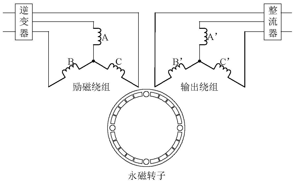
[0051] Specific implementation mode two, the following combination Figure 2 ~ Figure 6 To illustrate this embodiment, the flywheel pulse synchronous generator system with embedded permanent magnet rotor in this embodiment is as figure 2 As shown, the system includes an input inverter, an input motor, an embedded permanent magnet rotor synchronous motor, an output rectifier, an excitation current adjustment unit and an inertial flywheel. The embedded permanent magnet rotor synchronous motor has two sets of multi-phase armature windings on the stator. -Input power winding and output power winding. The output terminal of the input inverter is connected to the lead wire of the input power winding of the synchronous motor with embedded permanent magnet rotor; the output terminal of the output power winding of the synchronous motor with embedded permanent magnet rotor is connected to the AC input terminal of the output rectifier, and the embedded permanent magnet rotor is synchronous...
specific Embodiment approach 3
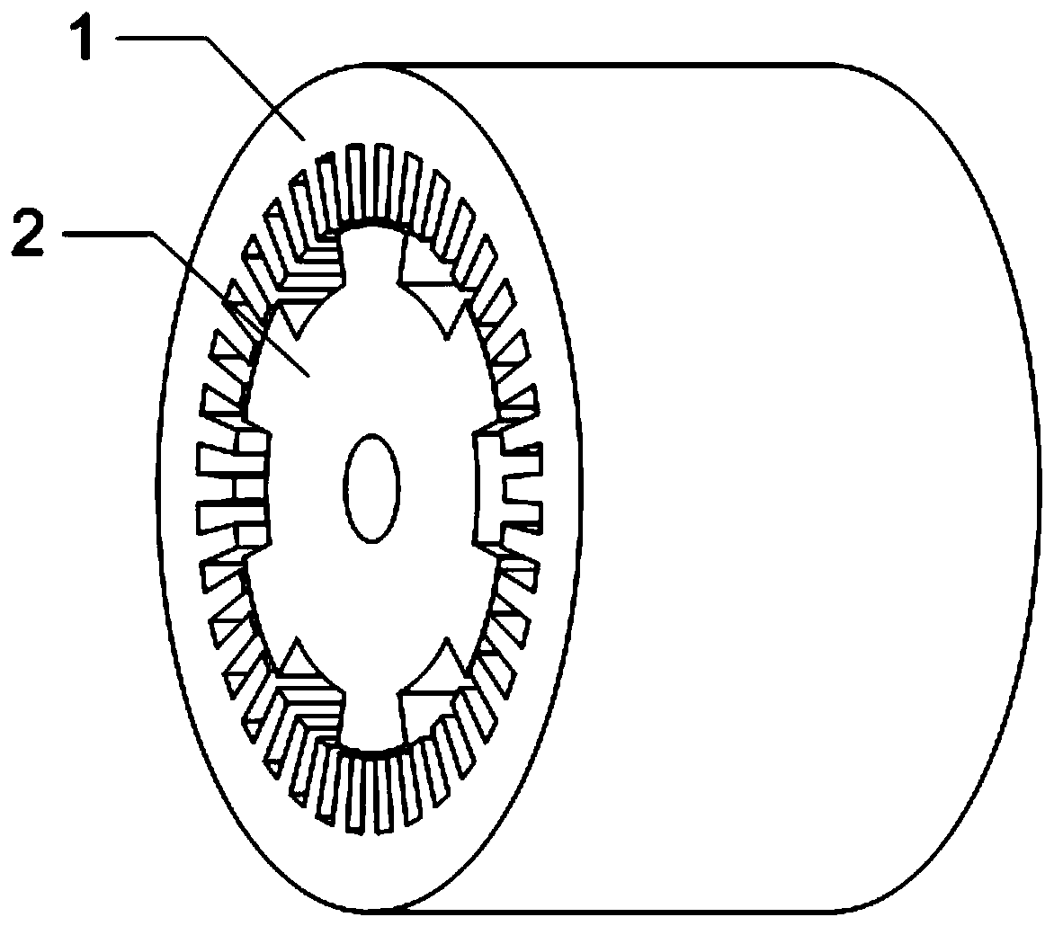
[0059] Specific implementation mode three, the following combination figure 2 , Figure 7 ~ Figure 10 To illustrate this embodiment, the flywheel pulse synchronous generator system with embedded permanent magnet rotor in this embodiment is as figure 2 As shown, the system includes an input inverter, an input motor, an embedded permanent magnet rotor synchronous motor, an output rectifier, an excitation current adjustment unit and an inertial flywheel. The embedded permanent magnet rotor synchronous motor has two sets of multi-phase armature windings on the stator. -Input power winding and output power winding. The output terminal of the input inverter is connected to the lead wire of the input power winding of the synchronous motor with embedded permanent magnet rotor; the output terminal of the output power winding of the synchronous motor with embedded permanent magnet rotor is connected to the AC input terminal of the output rectifier, and the embedded permanent magnet rotor...
PUM
 Abstract
Description
Claims
Application Information
 - R&D
- Intellectual Property
- Life Sciences
- Materials
- Tech Scout
- Unparalleled Data Quality
- Higher Quality Content
- 60% Fewer Hallucinations
Browse by: Latest US Patents, China's latest patents, Technical Efficacy Thesaurus, Application Domain, Technology Topic, Popular Technical Reports.
© 2025 PatSnap. All rights reserved.Legal|Privacy policy|Modern Slavery Act Transparency Statement|Sitemap|About US| Contact US: help@patsnap.com