Valve clamping device and valve clamping system

A valve and clamp technology, applied in the direction of heart valve, valve annulus, etc., can solve problems such as difficulty and time-consuming, and achieve the effect of reducing the difficulty of surgery and improving the efficiency of surgery

Pending Publication Date: 2019-11-26
HANGZHOU VALGEN MEDTECH CO LTD
View PDF0 Cites 15 Cited by
  • Summary
  • Abstract
  • Description
  • Claims
  • Application Information

AI Technical Summary

Problems solved by technology

However, since the two leaflets of the mitral valve are always in a state of opening and closing with a large range and force, it is difficult for the clamp to quickly and successfully capture the moving leaflet tissue, which makes doctors often spend a long time to complete an operation

Method used


Image

  • Valve clamping device and valve clamping system
  • Valve clamping device and valve clamping system
  • Valve clamping device and valve clamping system

Examples


Embodiment Construction

[0039] The following will clearly and completely describe the technical solutions in the embodiments of the present invention with reference to the drawings in the embodiments of the present invention. Wherein, the accompanying drawings are only used for exemplary illustration, and represent only schematic diagrams, and should not be understood as limitations on this patent.

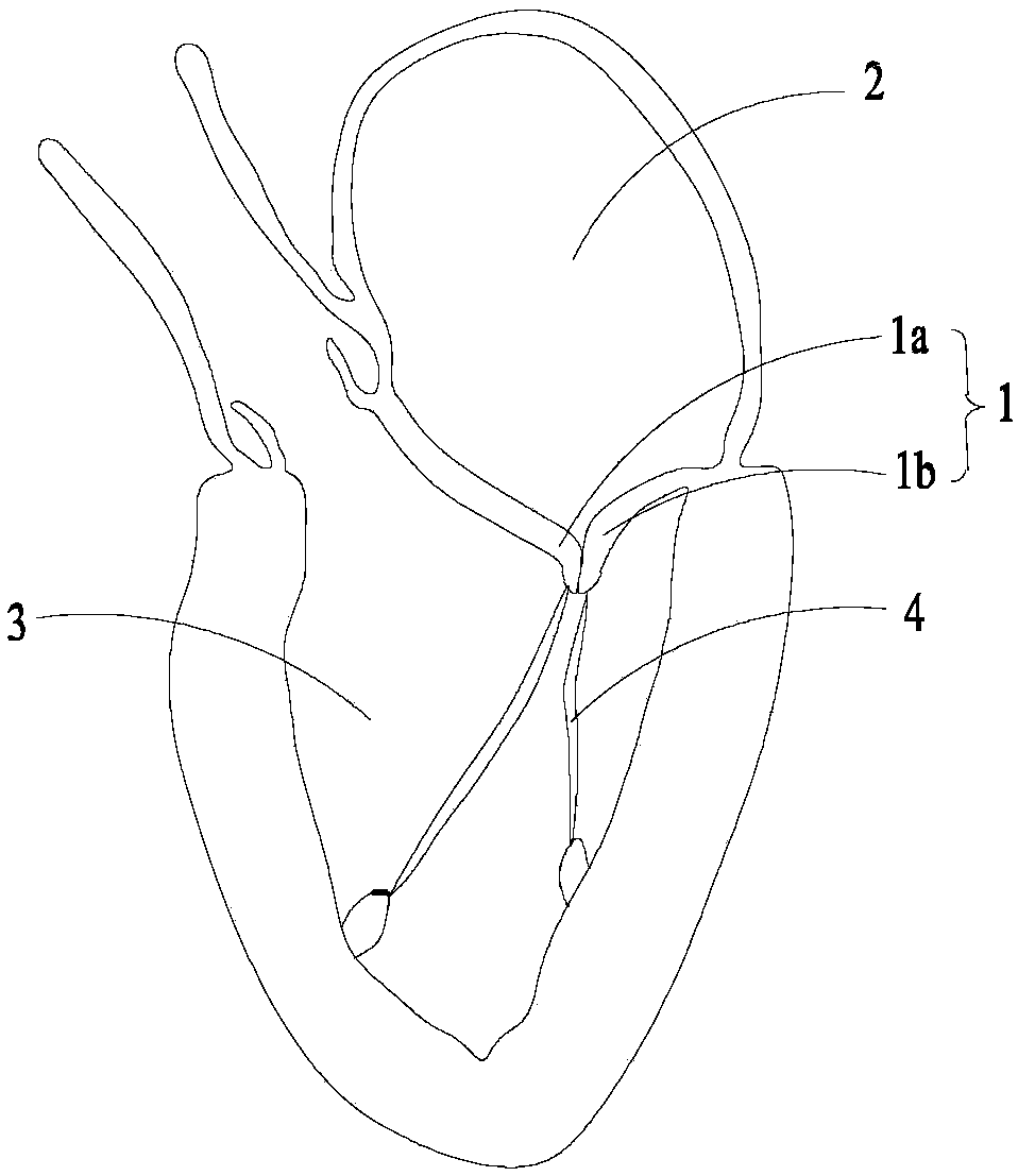
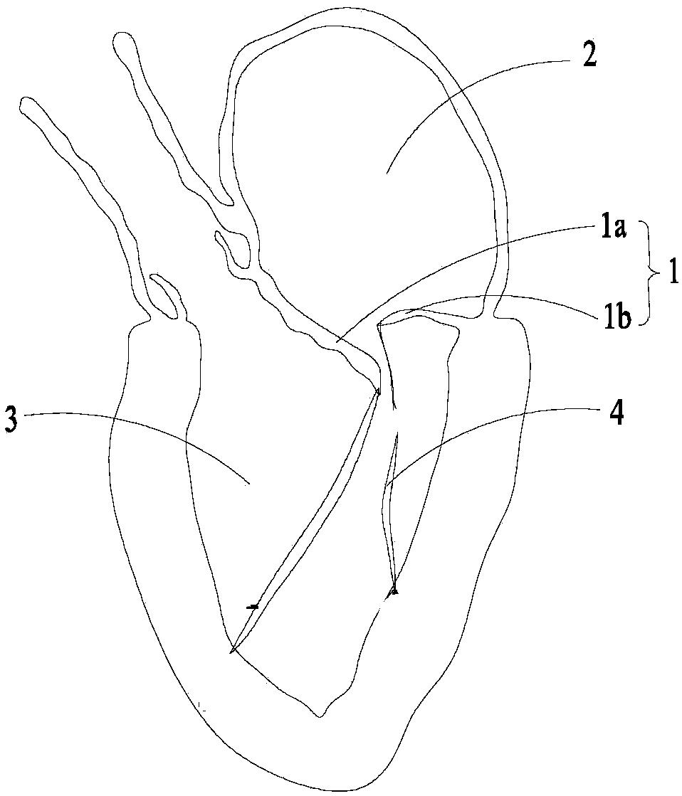
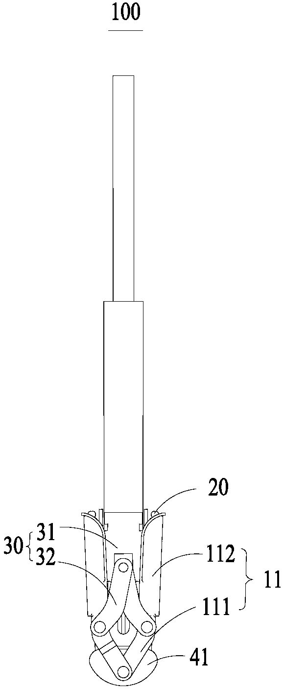
[0040] see Figure 3 to Figure 5, the present invention provides a valve clamp 100 . The valve clamp 100 includes a push rod 40 , at least two clamps 10 , at least one extension arm 20 and a driving assembly 30 . In this embodiment, the number of clamps 10 is two, and the two clamps 10 are symmetrically arranged with the push rod 40 as an axis. Specifically, see Image 6 , the valve clamp 100 is placed in the position A where the anterior leaflet and the posterior leaflet of the mitral valve cannot be properly aligned, so that one clamp 10 clamps the edge of the anterior leaflet 1a of the mitral valve...


PUM


Abstract

The invention provides a valve clamping device and a valve clamping system. The valve clamping system comprises the valve clamping device and a pushing device; the valve clamping device comprises a pushing rod, two or more clamps, one or more extension arms, and a driving assembly for driving the clamps to be opened and closed and driving the extension arms to stretch out and draw back; and each clamp comprises a first clamp arm and a second clamp arm which can be relatively opened and closed, and the one or more extension arms are arranged on the surfaces of the first clamp arms in stretchingout and drawing back modes. The extension arms capable of stretching out and drawing back are arranged on the surfaces of the first clamp arms of the valve clamping device, the extension arms stretchout of the first clamp arms while the first clamp arms are opened relative to the second clamp arms of the valve clamping device, the length of the first clamp arms of the clamps is increased equivalently, the long first clamp arms can support valves well when capturing the valves, the valves are prevented from slipping from the surfaces of the first clamp arms, thus the movable valves can be quickly captured, the surgery difficulty is lowered, and the surgery efficiency is improved.

Description

technical field [0001] The invention relates to the field of medical devices, in particular to a valve clipping device and a valve clipping system. Background technique [0002] see figure 1 , the mitral valve 1 is a one-way valve located between the left atrium 2 and the left ventricle 3 of the heart. A normal and healthy mitral valve 1 can control blood flow from the left atrium 2 to the left ventricle 3 while preventing blood flow from the left ventricle 3 to the left atrium 2. The mitral valve consists of a pair of leaflets, called the anterior leaflet 1a and the posterior leaflet 1b. The anterior leaf 1a and the posterior leaf 1b are fixed to the inner wall of the left ventricle 3 through the chordae 4 . Under normal circumstances, when the left ventricle of the heart contracts, the edges of the anterior lobe 1a and the posterior lobe 1b are completely joined to prevent blood from flowing from the left ventricle 3 to the left atrium 2 . see figure 2 , when the lea...

Claims


Application Information

Patent Timeline
Patent Type & Authority Applications(China)
IPC IPC(8): A61F2/24
CPCA61F2/2442A61F2/2466
Inventor 张庭超张伟伟郑贤章
Owner HANGZHOU VALGEN MEDTECH CO LTD
Why Eureka
Try Eureka