
New earth pressure balance shield machine and working method thereof

A technology of earth pressure balance and shield machine, which is applied in earthwork drilling, wellbore lining, tunnel lining, etc. It can solve the problems of not being able to find the construction site of the working well, and achieve the effects of increasing flow plasticity, reasonable combination, and great promotion prospects

Pending Publication Date: 2019-11-26
POWERCHINA RAILWAY CONSTR +2
View PDF0 Cites 6 Cited by
  • Summary
  • Abstract
  • Description
  • Claims
  • Application Information

AI Technical Summary

Problems solved by technology

[0005] However, nowadays, the settlement requirements of urban tunnel construction on the surface and through important buildings (structures) are getting higher and higher, and large-diameter shields are increasingly used in urban tunnels, but mud-water balance shield construction cannot find a suitable area in the city working well construction site

Method used


Image

  • New earth pressure balance shield machine and working method thereof
  • New earth pressure balance shield machine and working method thereof
  • New earth pressure balance shield machine and working method thereof

Examples


Embodiment 1

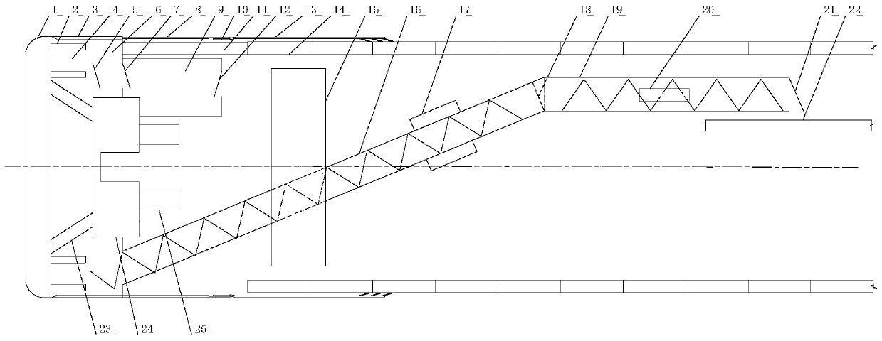
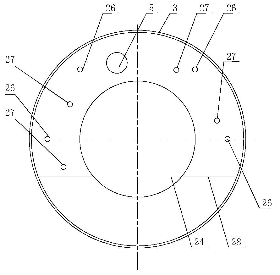
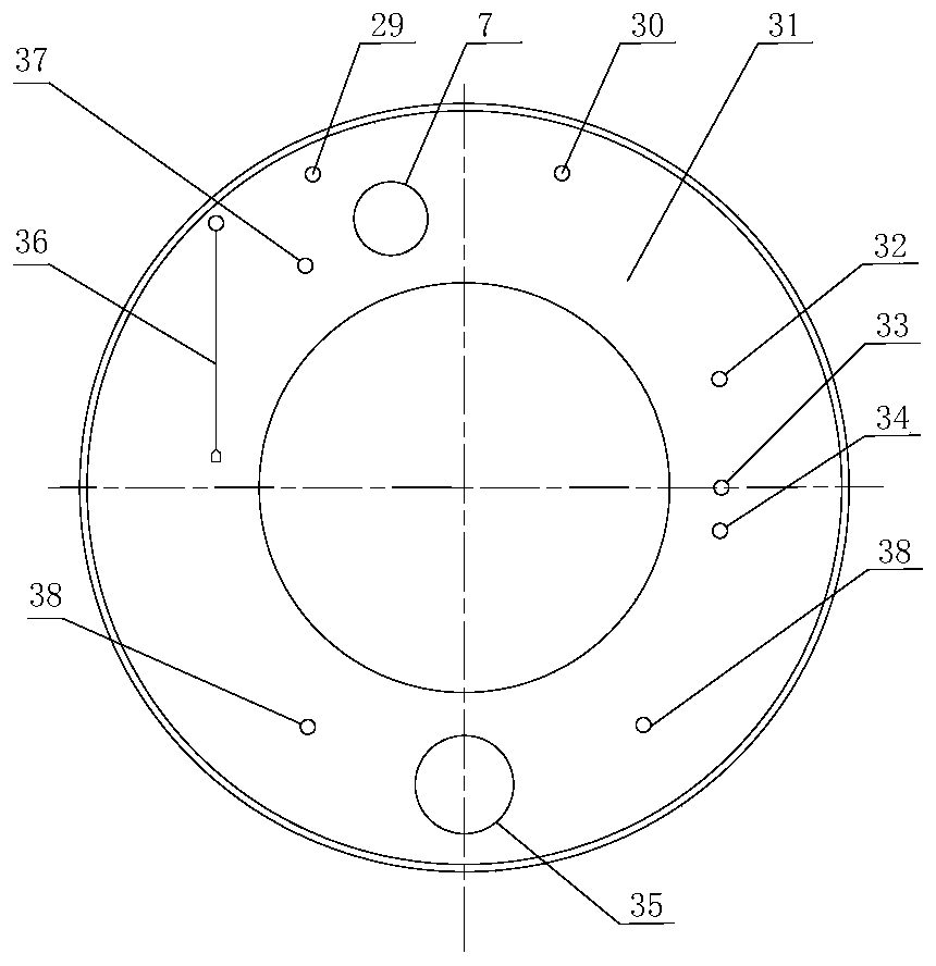
[0032] Such as figure 1 with figure 2 As shown, a new type of earth pressure balance shield machine includes cutter head 1, front shield 3, middle shield 8, man gate 9, shield tail 13, assembly machine 15, main drive 24 and screw conveyor, front shield 3 and A front shield partition 31 is installed between the middle shield 8, and a middle partition 28 is installed in the front shield 3 to divide the space of the front shield 3 into two parts. The front is a soil cabin 4, and the rear is an air cushion cabin 6; Closed; the cutter head 1 is connected with the large gear ring of the main drive 24 through the support arm 23; a hinged seal 10 is provided between the middle shield 3 and the shield tail 13.

[0033] The front shield partition 31 is provided with a first gate 7, an air inlet 30 and an exhaust port 29, a second gate 12 is provided on the access gate 9; an access door 5 is provided on the intermediate partition 28; the first gate 7 is provided in the front The upper part...

Embodiment 2

[0036] This embodiment is similar to the first embodiment, and the difference is that an active stirring rod 2 is installed behind the cutter head 1 and a passive stirring rod 26 is installed on the intermediate partition 28.

[0037] Alternatively, two stirring rods are arranged at the upper part of the rear of the cutter head 1, and two stirring rods are arranged at the lower part of the rear of the cutter head 1; the stirring rods are located on the vertical line of the cutter head 1. As the cutter head 1 rotates, the active stirring rod 2 rotates in the soil chamber 4 to stir the residue in the soil chamber 4, and a good stirring effect can also be achieved.

[0038] Such as figure 1 with figure 2 As shown, the position of the active stirring rod 2 and the position of the passive stirring rod 26 are staggered. Generally speaking, the muck is first stirred by the active stirring rod 2 and then pushed onto the passive stirring rod 26 for stirring. The two cooperate with each oth...

Embodiment 3

[0041] Traditional screw conveyors are often only set at one level, but due to the limited height of the shield machine, the transportation distance is often limited. The invention is equipped with a two-stage screw conveyor, which can transport a longer distance and ensures that the belt 22 can be arranged horizontally.

[0042] The screw conveyor includes two sections, the first section of the screw conveyor 16 and the second section of the screw conveyor 19; the first section of the screw conveyor 16 is arranged obliquely, and the front of the first section of the screw conveyor 16 is located on the front shield partition 31 slag conveying port 35; the second section of screw conveyor 19 is arranged horizontally. The first section of the screw conveyor 16 and the second section of the screw conveyor 19 may be connected by a spherical hinge 18 or a spherical joint, or may be connected by a soft rubber joint.

[0043] For the drive of the screw conveyor, a circular drive can be a...


PUM


Abstract

The invention discloses a new earth pressure balance shield machine and a working method thereof. The shield machine comprises a cutter head, a front shield, a middle shield, a miter gate, a tail shield, an assembling machine, a main drive and a screw conveyor. A front shield partition board is arranged between the front shield and the middle shield, front shield space is divided into two parts byinstalling a middle partition board in the front shield, the front is a mud chamber, and the rear is an air cushion chamber; the lower part of the middle partition board is not closed; the cutter head is connected with a big gear ring of the main drive by a support arm; a first gate, an air inlet and an overflow port are arranged on the front shield diaphragm board, and a second gate is arrangedon the miter gate; a passage gate and a passive mixing rod are arranged on the middle partition board; an active mixing rod is installed behind the cutter head; the first gate is arranged on the upperpart of the front shield partition board, and the lower part of the front shield partition board is provided with a slag conveying port. The new earth pressure balance shield machine is provided withthe mud chamber and the air cushion chamber, and a mud water balance shield play to the advantage. The shield machine further provides mixing rods, residual soil entering the mud chamber of the shield machine is stirred through the mixing rods, and flow plasticity of the residual soil is further increased.

Description

Technical field [0001] The invention relates to an earth pressure balance shield machine, in particular to a novel earth pressure balance shield machine combining the advantages of an earth pressure balance shield machine and a mud water balance shield machine and a working method. Background technique [0002] Nowadays, shield construction mainly adopts earth pressure balance shield and mud water balance shield. [0003] The advantages of using earth pressure balance shield construction are that the work well occupies a small area, the equipment cost and construction cost are low, and the construction progress is fast; the disadvantage is that the earth tank pressure control accuracy is not high, and sometimes the surface settlement after construction is large, and it is easy when the formation water is abundant. It causes spewing, and the shield cannot be tunneled normally. Therefore, the earth pressure balance shield is generally used in the construction of tunnels with small a...

Claims


Application Information

Patent Timeline
Patent Type & Authority Applications(China)
IPC IPC(8): E21D9/087E21D9/06E21D9/12E21D11/08
CPCE21D9/0873E21D9/0678E21D9/0642E21D9/0621E21D9/12E21D9/124E21D11/08
Inventor 王国义王婷雯蒋宗全王成孟庆明刘秀争房师涛
Owner POWERCHINA RAILWAY CONSTR
Learn More