Energy saving, water saving and cold and heat co-production device
A technology of cooling and heating, absorption device, applied in energy-saving heating/cooling, feed water heater, preheating and other directions, can solve the problems of small temperature difference between air-conditioning supply and return water, system operating cost and heat loss increase, and achieve high-efficiency energy-saving and emission reduction , the effect of alleviating the shortage of electricity and relieving primary energy consumption
- Summary
- Abstract
- Description
- Claims
- Application Information
AI Technical Summary
Problems solved by technology
Method used
Image

Examples
Embodiment 1
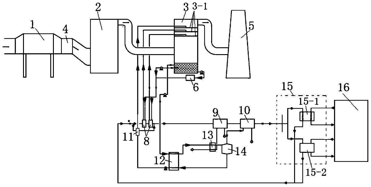
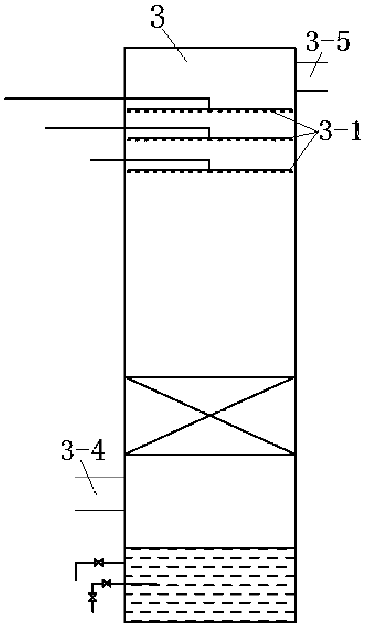
[0039] This embodiment provides an energy-saving water-saving and combined cooling and heating device, such as figure 1 and 2 As shown, it includes a dedusting device 1, a desulfurization device 2 and an absorption device 3 connected in sequence. For example, the dedusting device 1 can be an electric precipitator, the desulfurization device 2 can be a desulfurization tower, the absorption device 3 can be an absorption tower, and the absorption device 3 The lower part is provided with flue gas inlet 3-4, and the upper part is provided with flue gas outlet 3-5, which also includes,
[0040] At least one first circulation loop, the liquid inlet end of the first circulation loop communicates with the lower part of the absorption device 3, and the liquid outlet end communicates with the upper part of the absorption device 3, so that the liquid at the liquid outlet end enters the absorption device 3 and is connected with the absorption device 3. The flue gas in the absorption devic...
Embodiment 2
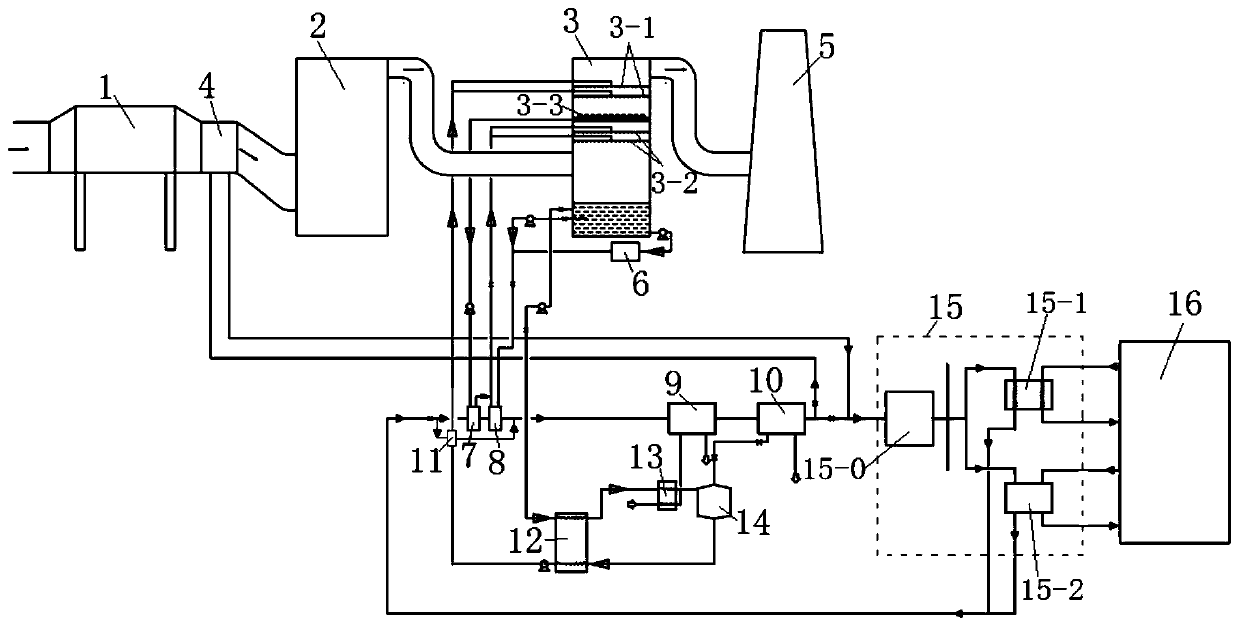
[0045] This embodiment provides an energy-saving, water-saving and combined cooling and heating device. On the basis of Embodiment 1, such as image 3 and 4 As shown, it also includes a liquid storage unit 3-3, for example, the liquid storage unit 3-3 can be a liquid receiving tray, such as Figure 4 As shown, the liquid receiving plate has a disk suitable for the inner cavity of the desulfurization tower, and a through hole is set on the disk. Along the axial direction of the desulfurization tower, the through hole has an extension section extending to the top of the desulfurization tower, and the adjacent extension section The space between them is the liquid storage space, which is arranged in the absorption device 3, and its inner cavity is divided into the first flue gas treatment area and the second flue gas treatment area, and the flue gas is suitable for passing through the liquid storage unit 3 from the first flue gas treatment area -3 enters the second flue gas trea...
Embodiment 3
[0057] This embodiment provides an energy-saving, water-saving and combined cooling and heating device. On the basis of the above-mentioned embodiment 1 or 2, in order to filter and modulate the concentrated absorption liquid in the absorption device, a solution filtration conditioning system 6 is also included. , the lower part of the absorption device 3, the solution filtration and conditioning system 6, the second heat exchanger 8, the first spray unit 3-1 and / or the second spray unit 3-2 are arranged in sequence in order to filter the dilute solution After conditioning and heat exchange, it is sent to the first spray unit 3-1 and / or the second spray unit 3-2; specifically, the solution filtration and conditioning system 7 is composed of cyclones + filters connected in sequence, while A solution replenishment tank and a fifth pump communicated in sequence are arranged, and the fifth pump communicates with the solution filtering and conditioning system to replenish the soluti...
PUM
 Abstract
Description
Claims
Application Information
 - R&D
- Intellectual Property
- Life Sciences
- Materials
- Tech Scout
- Unparalleled Data Quality
- Higher Quality Content
- 60% Fewer Hallucinations
Browse by: Latest US Patents, China's latest patents, Technical Efficacy Thesaurus, Application Domain, Technology Topic, Popular Technical Reports.
© 2025 PatSnap. All rights reserved.Legal|Privacy policy|Modern Slavery Act Transparency Statement|Sitemap|About US| Contact US: help@patsnap.com