Regeneration system for achieving deep utilization of sensible heat of raw flue gas

A regeneration system and original flue gas technology, applied in preheating, gas treatment, steam generation, etc., can solve the problems of waste of energy and water resources, inability to make deep use of a large amount of latent heat of raw flue gas, and large investment costs, so as to reduce operation cost, quality improvement, water saving effect

Pending Publication Date: 2019-03-01
CHINA HUADIAN ENG +1
View PDF5 Cites 1 Cited by
  • Summary
  • Abstract
  • Description
  • Claims
  • Application Information

AI Technical Summary

Problems solved by technology

[0004] Therefore, the technical problem to be solved by the present invention is that the existing technical route for recovering flue gas waste heat cannot make deep use of the sensible heat of the original flue gas and the large amount of latent heat of water vapor in the cleaned flue gas, and at the same time energy and water resources are wasted and the investment cost is high , to eliminate the defect that the colored plume has only investment but no income, and thus proposes a regeneration system for the deep utilization of raw flue gas sensible heat

Method used


Image

  • Regeneration system for achieving deep utilization of sensible heat of raw flue gas
  • Regeneration system for achieving deep utilization of sensible heat of raw flue gas
  • Regeneration system for achieving deep utilization of sensible heat of raw flue gas

Examples


Embodiment 1

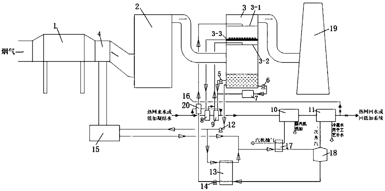
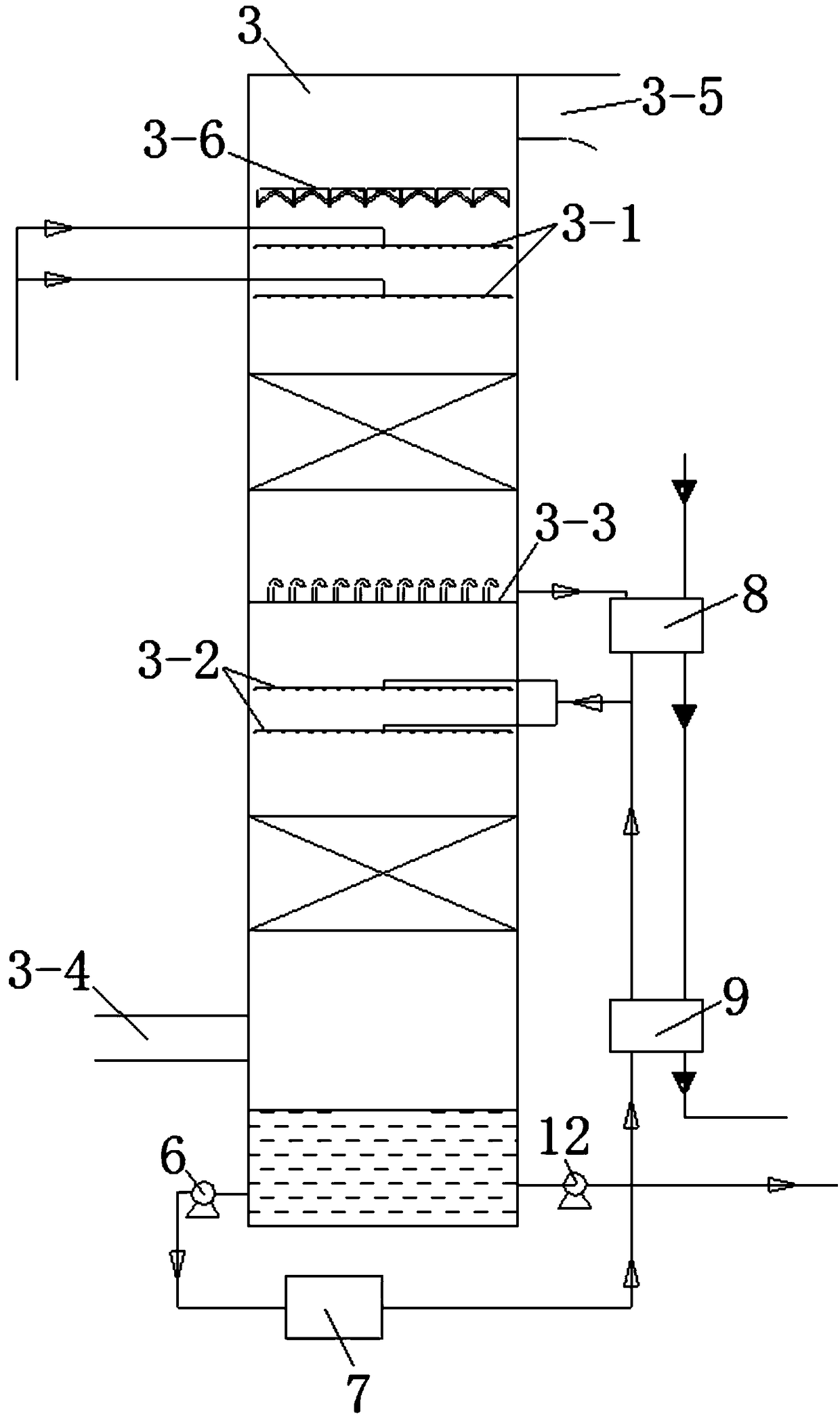
[0047] This embodiment provides a regeneration system for deep utilization of raw flue gas sensible heat, such as figure 1 with 2 As shown, it includes a dedusting device 1, a desulfurization device 2 and an absorption device 3 connected in sequence. For example, the dedusting device 1 can be an electric precipitator, the desulfurization device 2 can be a desulfurization tower, and the absorption device 3 can be an absorption tower. More specifically, it can be It is a spray tower or a packed tower, the lower part of the absorption device 3 is provided with a flue gas inlet 3-4, and the upper part is provided with a flue gas outlet 3-5, and also includes a liquid storage unit 3-3, for example, the liquid storage unit 3-3 can be a liquid disk, such as image 3 As shown, the liquid receiving plate has a disk suitable for the inner cavity of the desulfurization tower, and a through hole is set on the disk. Along the axial direction of the desulfurization tower, the through hole ...

Embodiment 2

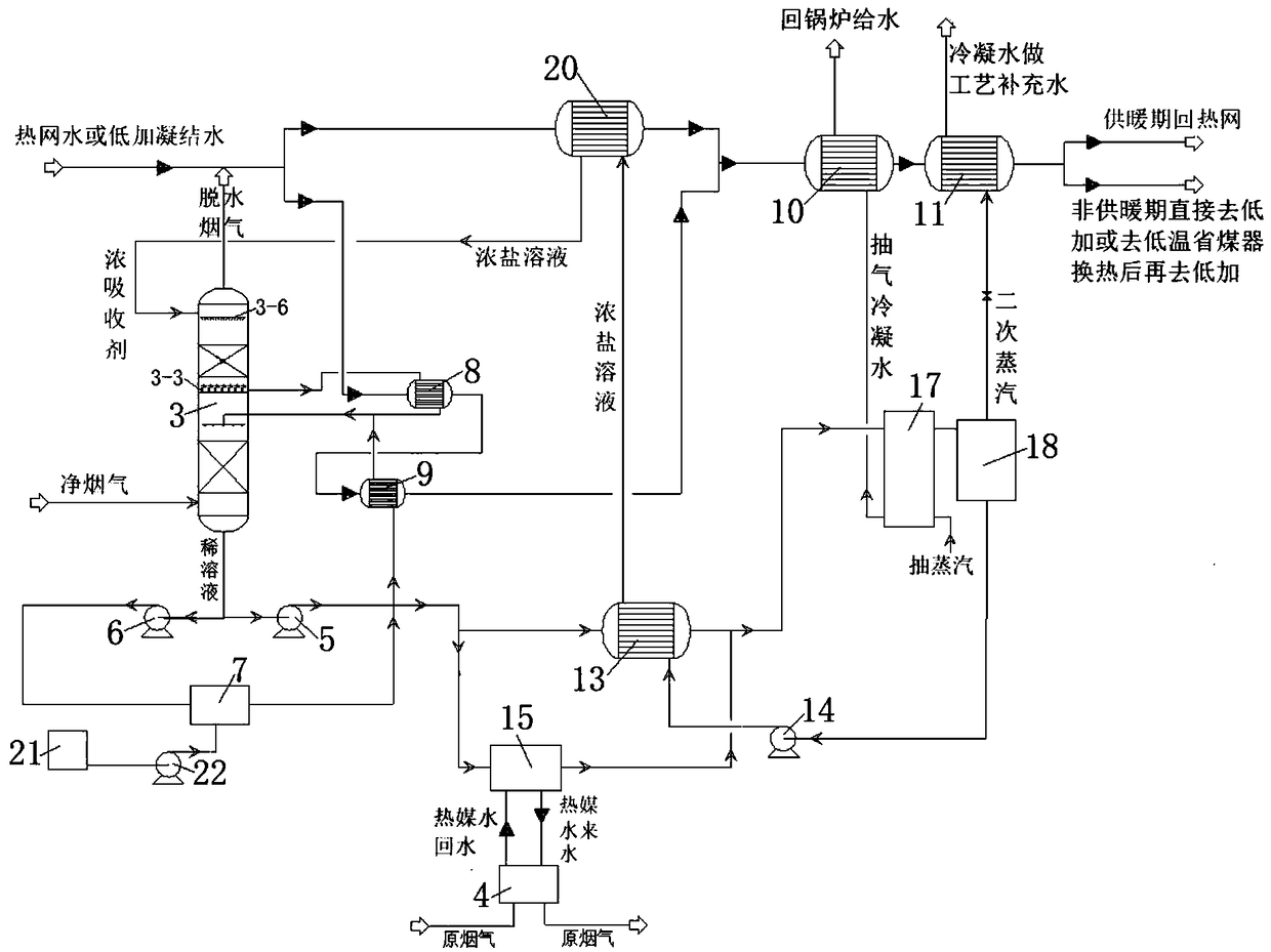
[0060] This embodiment provides a raw flue gas sensible heat deep utilization regeneration system. On the basis of the above-mentioned embodiment 1, in order to improve the heat exchange effect and fully recover the sensible heat in the raw flue gas and the latent heat of the clean flue gas water vapor, And the waste liquid is fully regenerated, and the second heat exchanger 9 is also included. The lower part of the absorption device 3, the second heat exchanger 9 and the second spray unit 3-2 are connected in sequence to send the dilute solution to the into the second spray unit 3-2; meanwhile, in order to filter and modulate the concentrated solution as the absorption liquid in the absorption device, it also includes a solution filtration and conditioning system 7, the bottom of the absorption device 3, the solution filtration and conditioning system 7, The second heat exchanger 9 and the second spray unit 3-2 are connected in sequence, so that the dilute solution is sent to ...

Embodiment 3

[0062]This embodiment provides a raw flue gas sensible heat deep utilization regeneration system, on the basis of the above-mentioned embodiment 1 or 2, it also includes a third heat exchanger 10 and a fourth heat exchanger 11, the first heat exchanger 8 , the second heat exchanger 9, the third heat exchanger 10 and the fourth heat exchanger 11 are connected in sequence, so that the incoming water from the heating network or the condensed water at low temperature can pass through the first heat exchanger 8 and the second heat exchanger 9 in sequence , the third heat exchanger 10 and the fourth heat exchanger 11, and exchange heat with the substances entering the corresponding heat exchanger;

[0063] As a variable embodiment, according to the primary steam condensed water temperature and the secondary steam temperature, the positions of the third heat exchanger 10 and the fourth heat exchanger 11 can be interchanged, specifically, the first heat exchanger 8 and the second heat ...


PUM


Abstract

The invention discloses a regeneration system for achieving deep utilization of sensible heat of raw flue gas. According to the regeneration system, a liquid storage unit is arranged in an absorbing device, an inner cavity is divided by the liquid storage unit into a first flue gas treatment area and a second flue gas treatment area, flue gas enters the bottom of the absorbing device to be in countercurrent contact with a concentrated solution sprayed to the top of the absorbing device, a concentrated solution in the second flue gas treatment area absorbs moisture in the flue gas and gets diluted, latent heat released in the moisture phase change process is discharged, and the flue gas and the concentrated solution are heated to 55-65 DEG C; the heated concentrated solution is guided out through the liquid storage unit and enters a first heat exchanger to exchange heat with a heat exchange medium such as heating network water, the heat exchange medium can be heated to 3-10 DEG C, the concentrated solution enters the first flue gas treatment area after being cooled to the temperature roughly coincident with that of a solution inlet of the top of the second flue gas treatment area, and the moisture in the flue gas continues to be absorbed. Firstly, gradient heat exchange is adopted, the heat exchange quality can be effectively improved, deep recycling is conducted, and the sensible heat of the raw flue gas and latent heat of water vapor of clean flue gas are deeply recycled.

Description

technical field [0001] The invention belongs to the technical field of environmental protection, and in particular relates to a regeneration system for deep utilization of raw flue gas sensible heat. Background technique [0002] At present, the mainstream technology for eliminating wet plume is to arrange the flue gas condenser, spray tower after the desulfurization tower, or add a slurry cooler on the slurry circulation slurry pipe to cool down the flue gas at the outlet of the desulfurization tower to precipitate moisture, and use the original flue gas Waste heat is used to heat the clean flue gas. This type of technology not only cannot deeply recover a large amount of latent heat of water vapor in the clean flue gas, but also wastes the sensible heat of the original flue gas. [0003] At the same time, the condensed water of the flue gas requires an external refrigerant, resulting in a great waste of energy. In order to take away the latent heat of the net flue gas, a ...

Claims


Application Information

Patent Timeline
Patent Type & Authority Applications(China)
IPC IPC(8): B01D53/18B01D53/14B01D50/00F22D1/34F23J15/06
CPCB01D53/1456B01D53/18F22D1/34F23J15/06B01D2258/0283B01D2251/404B01D50/10Y02E20/30
Inventor 王争荣汪洋
Owner CHINA HUADIAN ENG
Why Eureka
Try Eureka