A Unipolar Magnet Rotary Adjustable Speed ​​Cage Magnetic Coupler

A magnetic coupling and rotary technology, applied in the field of mechanical transmission, can solve the problems of large eddy current loss, failure to meet speed regulation requirements, small speed regulation range, etc., achieve small eddy current loss, increase service life, and improve transmission efficiency Effect

Active Publication Date: 2021-03-23
JIANGSU UNIV
View PDF4 Cites 0 Cited by
  • Summary
  • Abstract
  • Description
  • Claims
  • Application Information

AI Technical Summary

Problems solved by technology

[0003] In Chinese patent 20171041913.7, a disc-type speed-regulating magnetic coupler based on bevel gear transmission and its speed-regulating method are disclosed. The solid copper disc used in this invention has a circular shape with the same number of poles as the permanent magnet on its surface during operation. Induced current, the eddy current loss generated is relatively large. The principle of speed regulation is to convert the axial displacement of the dial block into the rotation of the large bevel gear sleeve, and realize the rotation of the permanent magnet through the meshing transmission of the bevel gear, thereby changing the permanent magnet and the conductor disk. The average facing area and air gap spacing between them also changed the arrangement of N and S poles, thereby changing the air gap flux density to achieve speed regulation, but due to the limitation of the rotation angle of the magnet, its speed regulation range Small, can not meet the speed regulation requirements of different degrees

Method used


Image

  • A Unipolar Magnet Rotary Adjustable Speed ​​Cage Magnetic Coupler
  • A Unipolar Magnet Rotary Adjustable Speed ​​Cage Magnetic Coupler
  • A Unipolar Magnet Rotary Adjustable Speed ​​Cage Magnetic Coupler

Examples


Embodiment Construction

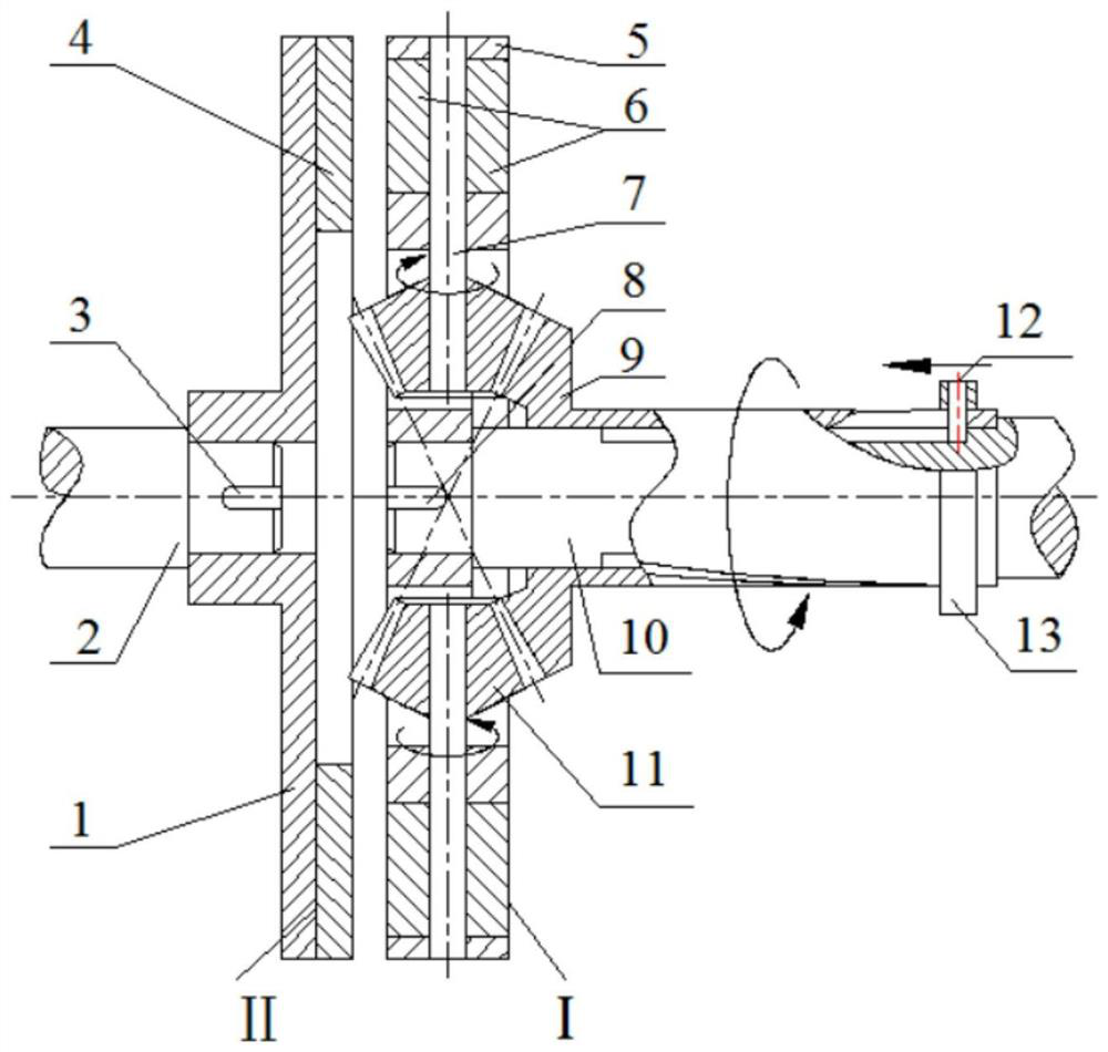
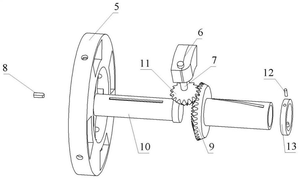
[0030] figure 1 Among them, the device is composed of driving disk assembly I and driven disk assembly II, and the speed regulating device is arranged on driving disk assembly I. figure 1 and figure 2 Among them, the driving disc assembly 1 includes a driving disc 5, an annular shifting block 13, a shifting block pin 12, a driving shaft 10, a large bevel gear sleeve 9, a small bevel gear 11, a pinion shaft 7 and a permanent magnet assembly 6 , the outer surface of the driving shaft 10 is covered with a large gear sleeve 9, and the right end is covered with an annular shifting block 13, Figure 4 Among them, the surface of the ring shifting block 13 is processed with symmetrically distributed circular radial through holes, image 3 Among them, the surface of the drive shaft 10 and the large bevel gear sleeve 9 are respectively symmetrically processed with straight grooves and oblique grooves, and the shift pin 12 is symmetrically inserted in the radial circular through hole ...


PUM


Abstract

The invention relates to the field of mechanical transmission, and relates to a unipolar magnet rotary adjustable speed cage magnetic coupler. In the present invention, the copper disk adopts a cage-shaped copper disk, and fan-shaped annular currents are generated around all the fan-shaped grooves, and the eddy current loss generated by it is small, and the transmission efficiency is high. The bump is an interference fit, and the small bump of the yoke plays a role in modulating the magnetic field, further improving the electromagnetic torque of the coupler. The coupler provides three speed regulation methods, the first is to adjust the size of the air gap between the copper disk and the permanent disk through the axial movement device, the second is to fix the size of the air gap to change the rotation angle of the rotating permanent magnet to adjust the conductor The facing area between the disk and the permanent magnet disk, the third is to use the composite speed regulation of the air gap size between the two disks moving axially and the rotating permanent magnet, so the coupler can meet the speed regulation requirements of different degrees.

Description

technical field [0001] The invention relates to the field of mechanical transmission, and relates to a magnetic transmission and speed regulating device that realizes torque transmission through non-contact induction, in particular to a unipolar magnet rotary adjustable speed cage magnetic coupler. It can be used as a transmission device for torque transmission and speed regulation between a motor with a large vibration and a load. Background technique [0002] The magnetic coupling utilizes the mutual coupling of the permanent magnetic field and the induced magnetic field to transmit torque. Its unique non-contact transmission can effectively reduce the problems of noise, vibration, friction and wear in traditional mechanical transmission, and greatly improve the performance of the transmission device. In addition, it has the function of energy saving and environmental protection. Based on the above advantages, magnetic couplers have been widely used in chemical industry, m...

Claims


Application Information

Patent Timeline
Patent Type & Authority Patents(China)
IPC IPC(8): H02K49/10
CPCH02K49/108H02K49/046H02K7/116
Inventor 杨超君孙佳杰吴俊陈子清彭志卓朱莉邰蒋西
Owner JIANGSU UNIV
Why Eureka
Try Eureka