
Level conversion circuit

A technology for converting circuits and levels, which is applied in the direction of logic circuits, logic circuit interface devices, logic circuit connection/interface layout, etc., and can solve the problem of weak pull-down capability of high-voltage NMOS transistors, inability to realize level conversion, and failure of level conversion circuits to work And other issues

Pending Publication Date: 2019-11-26
SHANGHAI HUALI MICROELECTRONICS CORP
View PDF6 Cites 6 Cited by
  • Summary
  • Abstract
  • Description
  • Claims
  • Application Information

AI Technical Summary

Problems solved by technology

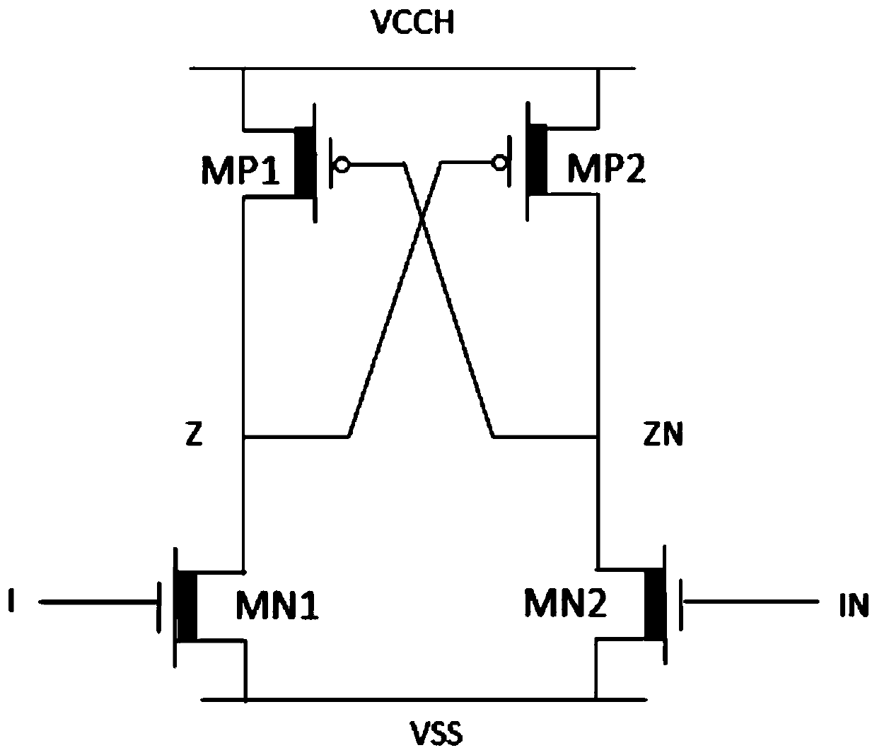
Since the two high-voltage NMOS transistors work at low voltage, the pull-down capability of the two high-voltage NMOS transistors is very weak. When the low voltage value is low to a certain extent, the level conversion circuit cannot work, that is, the function of level conversion cannot be realized.

Method used


Image

  • Level conversion circuit
  • Level conversion circuit
  • Level conversion circuit

Examples


no. 1 example

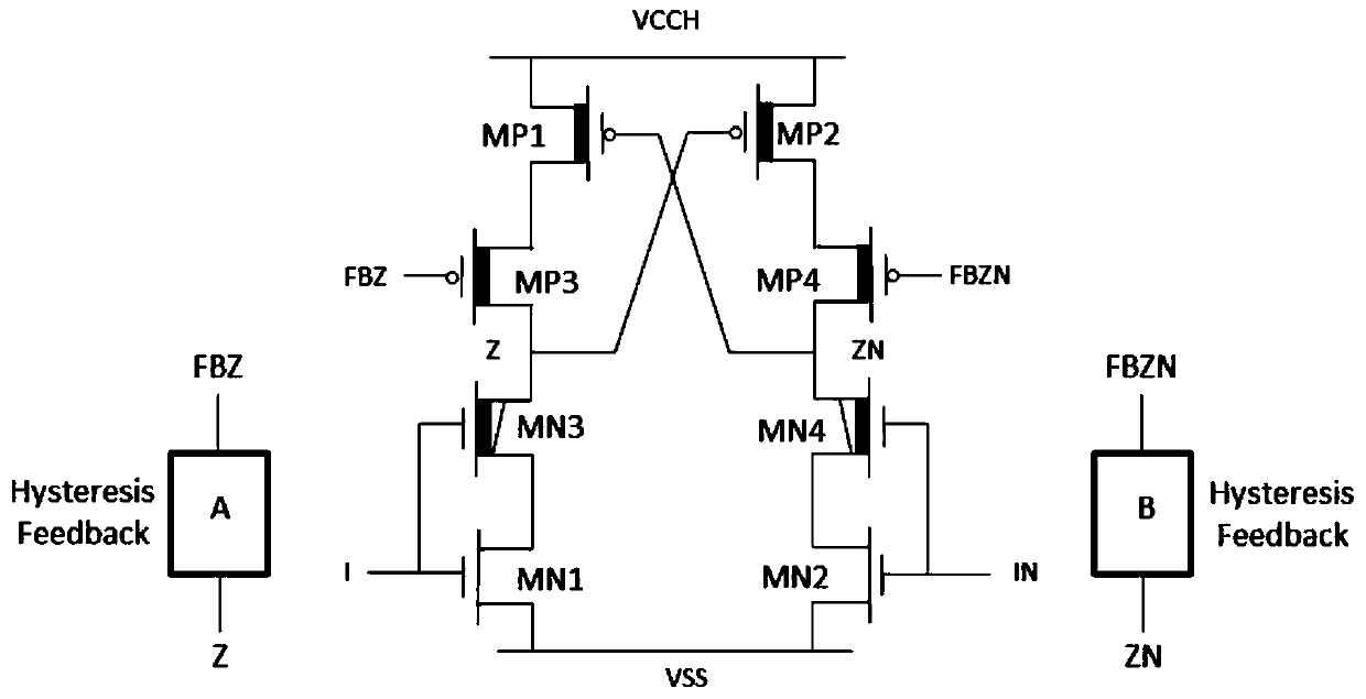
[0068] Such as figure 2 As shown, the first embodiment of the level conversion circuit provided by the present invention includes:

[0069] The source of the first NMOS transistor MN1 is grounded to VSS, its drain is connected to the source of the third NMOS transistor MN3, and its gate is connected to the gate of the third NMOS transistor MN3 as the first low-voltage input terminal I;

[0070] The source of the second NMOS transistor MN2 is grounded to VSS, its drain is connected to the source of the fourth NMOS transistor MN4, and its gate is connected to the gate of the fourth NMOS transistor MN4 as the second low-voltage input terminal IN,

[0071] The drain of the third NMOS transistor MN3 is connected to the gate of the second PMOS transistor MP2, the drain of the third PMOS transistor MP3 and the input terminal of the first hysteresis feedback circuit A, and serves as the first high voltage output terminal Z;

[0072] The fourth NMOS transistor MN4, the drain of which ...

no. 2 example

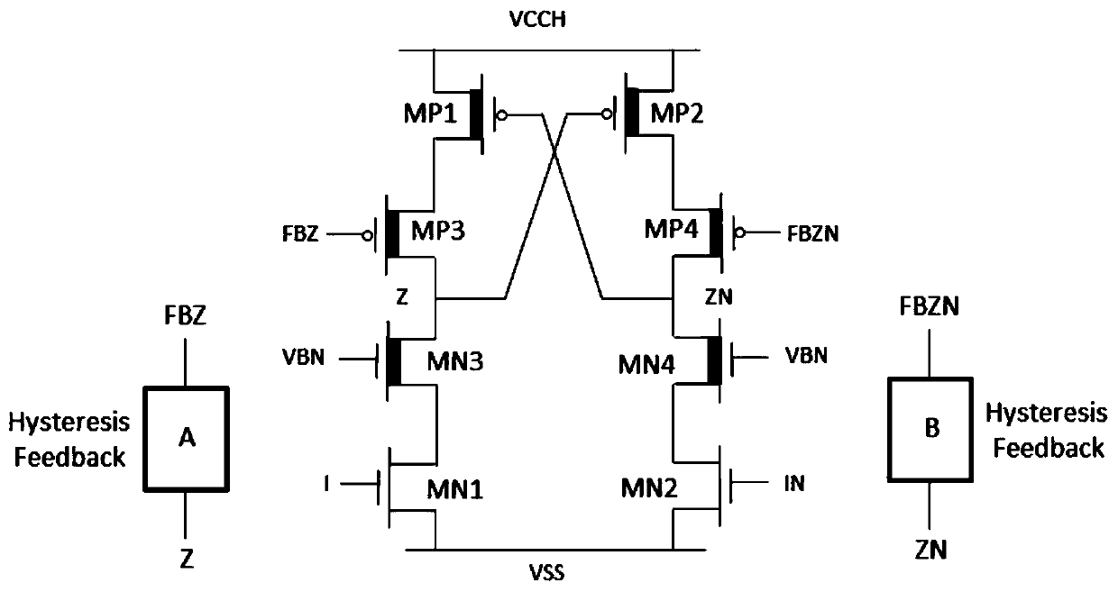
[0085] Such as image 3 As shown, the present invention provides a second embodiment of a level conversion circuit, including:

[0086] The source of the first NMOS transistor MN1 is grounded to VSS, its drain is connected to the source of the third NMOS transistor MN3, and its gate serves as the first low-voltage input terminal I;

[0087] The source of the second NMOS transistor MN2 is grounded to VSS, its drain is connected to the source of the fourth NMOS transistor MN4, and its gate is used as the second low-voltage input terminal IN;

[0088] The drain of the third NMOS transistor MN3 is connected to the gate of the second PMOS transistor MP2, the drain of the third PMOS transistor MP3 and the input terminal of the first hysteresis feedback circuit A and serves as the first high-voltage output terminal Z, and its gate is connected to the medium voltage bias Set potential VBN;

[0089] The fourth NMOS transistor MN4, its drain is connected to the gate of the first PMOS ...


PUM


Abstract

The invention discloses a level conversion circuit, which comprises that a first NMOS (N-channel metal oxide semiconductor) source electrode is grounded, a drain electrode is connected with a third NMOS source electrode, and a grid electrode serves as a first low-voltage input end, the source electrode of the second NMOS is grounded, the drain electrode is connected with the source electrode of the fourth NMOS, and the grid electrode is used as a second low-voltage input end; the drain electrode of the third NMOS is connected with the grid electrode of the second PMOS, the drain electrode of the third PMOS and the input end of the first hysteresis feedback circuit serve as a first high-voltage output end, and the grid electrode of the third NMOS is connected with a medium-voltage bias potential; the drain electrode of the fourth NMOS is connected with the grid electrode of the first PMOS, the drain electrode of the fourth PMOS and the input end of the second hysteresis feedback circuitserve as a second high-voltage output end, and the grid electrode of the fourth NMOS is connected with a medium-voltage bias potential; the source electrode of the first PMOS is connected with a high-voltage power supply, and the drain electrode of the first PMOS is connected with the source electrode of the third PMOS; the source electrode of the second PMOS is connected with a high-voltage power supply, and the drain electrode of the second PMOS is connected with the source electrode of the fourth PMOS; the grid electrode of the third PMOS is connected with the output end of the first hysteresis feedback circuit; the grid electrode of the fourth PMOS is connected with the output end of the second hysteresis feedback circuit; the first to fourth NMOS body regions are grounded, and the first to fourth PMOS bodies are connected with a high-voltage power supply. The level conversion circuit can normally work under the condition of being close to the threshold voltage of the device.

Description

technical field [0001] The invention relates to the field of integrated circuits, in particular to a level conversion circuit. Background technique [0002] The level conversion circuit includes a high-voltage level conversion circuit and a low-voltage level conversion circuit, wherein the high-voltage level conversion circuit converts the low-voltage control signal into a high-voltage control signal to realize the control of the low-voltage logic on the high-voltage power output pole. Generally, according to the polarity of the output high-voltage control signal, the level shifting circuit can be divided into a negative voltage level shifting circuit and a positive voltage level shifting circuit. A traditional level-shifting circuit consists of four high-voltage transistors. Two high-voltage PMOS transistors are used for pull-up, and two high-voltage NMOS transistors are used for pull-down. The gates of the two high-voltage NMOSs are used as two input terminals of the lev...

Claims


Application Information

Patent Timeline
Patent Type & Authority Applications(China)
IPC IPC(8): H03K19/0185
CPCH03K19/017509H03K19/018507H03K19/0013
Inventor 浦珺慧
Owner SHANGHAI HUALI MICROELECTRONICS CORP
Learn More