
Chimney waste gas smoke plume removal apparatus utilizing electrostatic technology

A waste gas and chimney technology, applied in the field of high-voltage static electricity, can solve the problems of large water consumption, poor dispersion effect, low whitening efficiency, etc., and achieve the effect of simple working principle, cost saving and simple structure

Pending Publication Date: 2019-11-29
JIANGSU UNIV
View PDF10 Cites 3 Cited by
  • Summary
  • Abstract
  • Description
  • Claims
  • Application Information

AI Technical Summary

Problems solved by technology

Judging from the current technology, the pre-treatment methods that are widely used are: "water-cooled" condensing device and spray device, but "water-cooled" condensing device mostly uses circulating water to take away the heat in the exhaust gas, and then uses it in the cooling tower. Evaporation of circulating water will consume a lot of water resources; most of the spraying devices use pressure spraying, the dispersion effect is relatively poor, and the whitening efficiency is low

Method used


Image

  • Chimney waste gas smoke plume removal apparatus utilizing electrostatic technology
  • Chimney waste gas smoke plume removal apparatus utilizing electrostatic technology
  • Chimney waste gas smoke plume removal apparatus utilizing electrostatic technology

Examples


Embodiment Construction

[0023] In order to make the object, technical solution and advantages of the present invention clearer, the present invention will be further described in detail below in conjunction with the accompanying drawings and embodiments. It should be understood that the specific embodiments described here are only used to explain the present invention, not to limit the present invention.

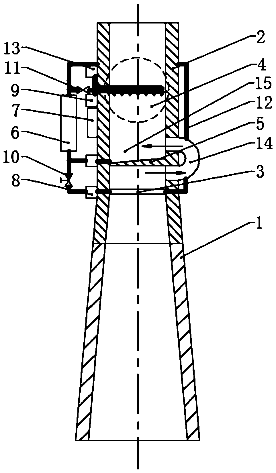
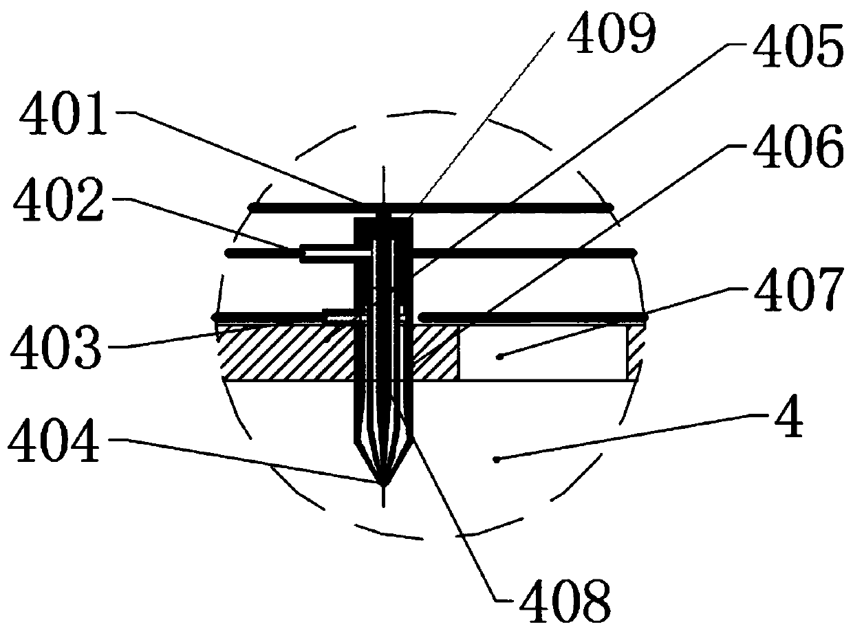
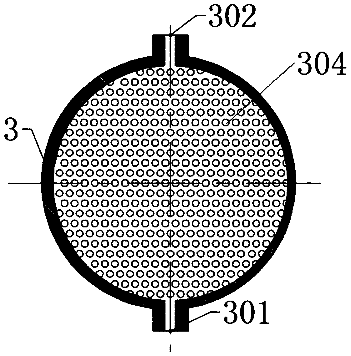
[0024] The present invention has designed a chimney waste gas dewhitening device utilizing electrostatic technology, such as figure 1 As shown, the cylindrical dewhitening device 2 is installed at the end of the chimney 1, and the condensing atomization device 3, the water collection tank 5 and the electrostatic atomization nozzle unit 4 are sequentially installed inside the dewhitening device 2 from bottom to top; the water collection tank 5 and The space between the electrostatic atomization nozzle units 4 is a dewhitening chamber 15 , and the space between the condensation atomization device 3 a...


PUM

PropertyMeasurementUnit
Slope angleaaaaaaaaaa

Abstract

The invention discloses a chimney waste gas smoke plume removal apparatus utilizing an electrostatic technology. The chimney waste gas smoke plume removal apparatus comprises a smoke plume removal device installed at the end of a chimney, wherein a condensation atomization device, a water collecting groove and an electrostatic atomization spraying nozzle unit are sequentially arranged in the smokeplume removal device from bottom to top, a smoke plume removal chamber is arranged between the water collecting groove and the electrostatic atomization spraying nozzle unit, and the space between the condensation atomization device and the water collecting groove is communicated to the smoke plume removal chamber through a flow guide pipe. According to the present invention, the condensation atomization device performs heat exchange on waste gas through a cooling liquid, such that the waste gas is atomized after penetrating through the condensation atomization device; the atomized waste gasenters the smoke plume removal chamber through the flow guide pipe; the electrostatic atomization spraying nozzle unit make the atomized waste gas in the smoke plume removal chamber settle through electrostatic spraying; the settled liquid droplets are collected by the water collecting groove; the cooling liquid of the condensation atomization device and the liquid collected by the water collecting groove are cooled by the cooling device, and then enter the condensation atomization device and the electrostatic atomization spraying nozzle unit again so as to start the next cycle; and the chimney waste gas smoke plume removal apparatus of the present invention has good smoke plume removal effect and low energy consumption.

Description

technical field [0001] The invention belongs to the technical field of high-voltage static electricity, and in particular relates to a chimney exhaust gas whitening device using electrostatic technology. Background technique [0002] At present, white smoke from tall chimneys can still be seen in most cities in China. The smoke mainly comes from coal-fired power plants, chemical industries, steel plants, textile and paper industries. Most of these flue gases are saturated wet flue gas discharged after desulfurization treatment, and there is a large amount of water vapor in the flue gas. If these flue gases are directly discharged into the atmosphere, the water vapor will condense to form a wet plume. It not only affects the aesthetic feeling of the city, but also causes great pollution to the environment, so it is necessary to de-whiten the places where white smoke is produced. [0003] At present, most of the technologies for de-whitening high-humidity exhaust gas are pre-...

Claims


Application Information

Patent Timeline
IPC IPC(8): B01D53/00B01D50/00B03C3/017
CPCB01D53/002B01D50/00B03C3/017
Inventor 刘海龙刘志伟沈学峰王军锋
Owner JIANGSU UNIV
Learn More