A material transmission method, transmission device, transmission system and readable storage medium

A material transmission system and material transmission technology, applied in the field of automated production of electronic products, can solve the problems of increasing the running distance of the PCB board and decreasing the detection efficiency.

Active Publication Date: 2021-10-29
JOINT STARS TECH
View PDF6 Cites 0 Cited by
  • Summary
  • Abstract
  • Description
  • Claims
  • Application Information

AI Technical Summary

Problems solved by technology

[0005] In view of this, an embodiment of the present invention provides a material transmission method, a transmission device, a transmission system, and a readable storage medium to solve the problems

Method used


Image

  • A material transmission method, transmission device, transmission system and readable storage medium
  • A material transmission method, transmission device, transmission system and readable storage medium
  • A material transmission method, transmission device, transmission system and readable storage medium

Examples


Embodiment 1

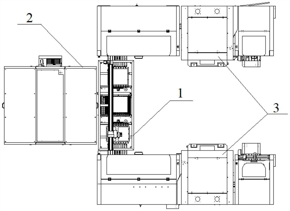
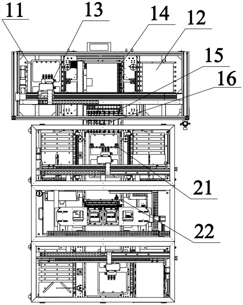
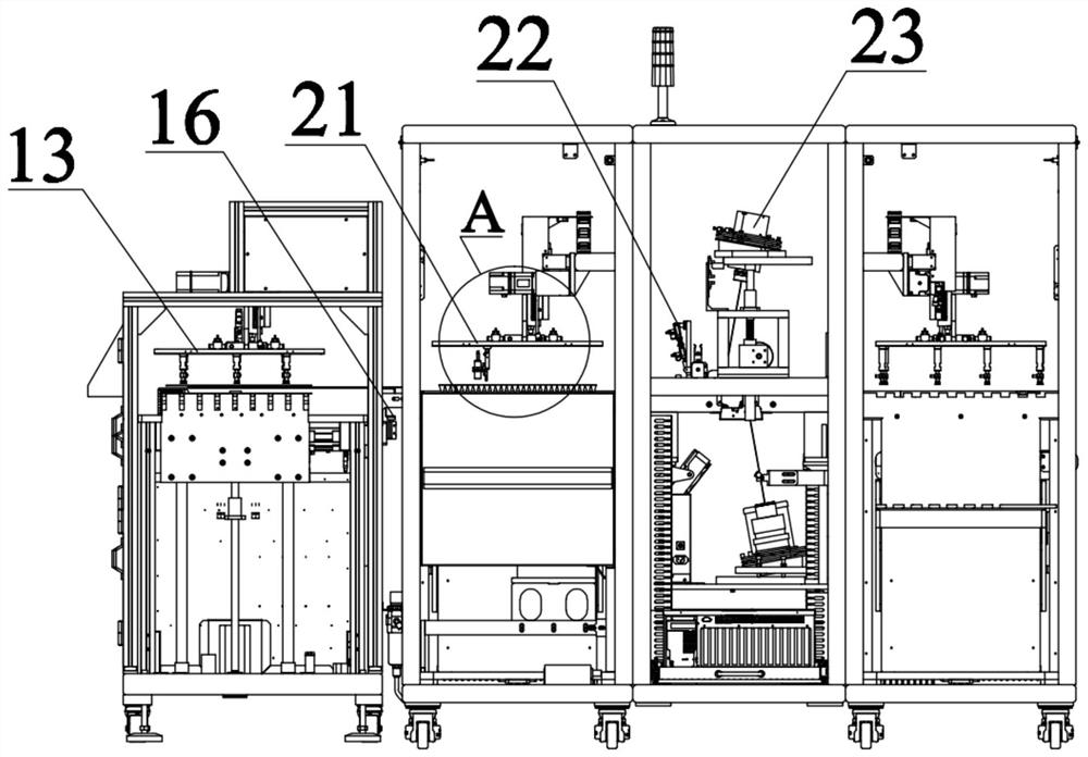
[0052] figure 2 Shows a flow chart of a material transfer method according to an embodiment of the present invention, which can be used but not limited to Figure 1A-Figure 1H Shown is the conversion platform and detection equipment interfaced with the output of the conversion platform. Such as figure 2 As shown, the material transfer method includes the following steps:

[0053] S201: Control the material to be transported to be transported to the transport surface of the first transport mechanism.

[0054] Here, when applied to Figure 1A-Figure 1H For the equipment shown, the transmission of the material to be transmitted to the first transmission mechanism can be controlled by controlling the feeding mechanism to absorb the material to be conveyed, and controlling the feeding mechanism to move above the first output mechanism and then release the material to be conveyed face. Of course, this method is not limited to Figure 1A-Figure 1H The device shown, for exampl...

Embodiment 3

[0110] Figure 5 A schematic block diagram of a material conveying device according to an embodiment of the present invention is shown, and the device can be used to implement the material conveying method described in Embodiment 1 or any optional implementation thereof. Such as Figure 5 As shown, the device includes: a feeding control module 10 , a first lifting control module 20 , a waiting judging module 30 , a second lifting control module 40 and a material transmission module 50 .

[0111] The feeding control module 10 is used to control the material to be transported to be transported to the conveying surface of the first conveying mechanism.

[0112] The first lifting control module 20 is used for controlling the lifting mechanism to drive the material to be conveyed to move along the first direction, so that the material to be conveyed is separated from the conveying surface.

[0113] The waiting judging module 30 is used to judge whether there is material at the fi...


PUM


Abstract

The invention discloses a material transmission method, a transmission device, a transmission system and a readable storage medium. The method includes: controlling the transmission of the material to be transmitted to the transmission surface of the first transmission mechanism; controlling the lifting mechanism to drive the material to be transmitted along the first Direction movement, so that the material to be conveyed is separated from the conveying surface; judge whether there is material at the first baffle; wherein, the first baffle is set at the discharge position of the first transmission mechanism; when there is no material at the first baffle, Controlling the lifting mechanism to move along the second direction, so that the materials to be conveyed fall onto the conveying surface; wherein, the first direction is opposite to the second direction; controlling the first conveying mechanism to convey the materials to the first baffle. By implementing the invention, when the detection equipment docked with the output end of the conversion platform is waiting for the material to be transported to be transported to the detection position, the running distance of the material to be detected is shortened from the first baffle to the detection position. The distance can improve the detection efficiency of the detection equipment.

Description

technical field [0001] The invention relates to the technical field of automatic production of electronic products, in particular to a material transmission method, a transmission device, a transmission system and a readable storage medium. Background technique [0002] With the rapid development of electronic technology, printed circuit boards (Printed Circuit Board, PCB) are widely used in various fields. PCB boards are essential components in the modern electronics industry. support carrier. In order to ensure the normal operation of electronic equipment and reduce mutual electromagnetic interference, the printed circuit board after processing and manufacturing must be inspected to check whether the performance of the printed circuit board meets the requirements. With the development of science and technology, PCB board production and quality inspection equipment have appeared on the market. The use of equipment can realize automatic production and inspection of PCB boar...

Claims


Application Information

Patent Timeline
IPC IPC(8): B65G49/06B65G43/08B65G47/74B65G47/91B65G47/90H05K3/00G01R31/28
CPCB65G43/08B65G47/74B65G47/902B65G47/914B65G49/061G01R31/2808H05K3/00
Inventor 陈姣申璐迪
Owner JOINT STARS TECH
Why Eureka
Try Eureka