Synchronous motion-based roundness error separation device

A roundness error and separation device technology, applied in the direction of measuring devices, instruments, etc., can solve the principle error of the model, the radial rotation error error separation of the rotating shaft radial rotation error of the ultra-precision roundness measuring instrument, the radial rotation error of the turntable, and complex calculations, etc. problem, to achieve the effect of less calculation steps, fast detection speed and simple calculation

Inactive Publication Date: 2019-11-29
正斌超市平阳有限公司
View PDF11 Cites 4 Cited by
  • Summary
  • Abstract
  • Description
  • Claims
  • Application Information

AI Technical Summary

Problems solved by technology

But the disadvantages are also obvious. For example, the increase in the number of sensors will lead to inconsistent characteristics of each sensor, the layout of the sensors is not on the same measurement section, and there are problems such as zero points in the transfer function.
[0012] The problems in the above method are: 1. The signal is transformed into the frequency domain by Fourier transform for error separation, and the spectrum information of the separated signal is obtained, and then the inverse Fourier transform is performed to finally obtain the separated signal. The calculation is complicated and has Truncation and rounding errors; 2. Due to the use of Fourier transform, there is a problem of harmonic suppression in the separated signal, and there is a principle error in the model. The corresponding improvement method can only solve the problem of no harmonic suppression in a certain range, and cannot achieve full There is no harmonic suppression in the band; 3. The roundness error of the measured piece, the radial rotation error of the rotating shaft of the ultra-precision roundness measuring instrument and the radial rotation error of the error separation turntable cannot be separated at the same time

Method used


Image

  • Synchronous motion-based roundness error separation device
  • Synchronous motion-based roundness error separation device
  • Synchronous motion-based roundness error separation device

Examples


specific Embodiment approach 1

[0050] The following embodiment is an embodiment of a circularity error separation device based on synchronous motion in the present invention.

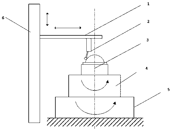
[0051] A synchronous movement-based roundness error separation device in this embodiment, the structural diagram is as follows figure 1 shown. The circularity error separation device based on synchronous motion includes a transverse guide rail 1, a displacement sensor 2, an error separation turntable 4, a rotary table 5 and a vertical guide rail 6, the displacement sensor 2 moves horizontally on the transverse guide rail 1, and the transverse guide rail 1 Drive the displacement sensor 2 to move up and down along the vertical guide rail 6, the error separation turntable 4 is placed flat on the rotary table 5, the error separation turntable 4 rotates together with the tested part 3, and the rotary table 5 drives the error separation turntable 4 and the tested part 3 coaxial rotation.

[0052] The rotary table 5 is in the form of hydr...

specific Embodiment approach 2

[0055] The following embodiment is an embodiment of a circularity error separation method based on synchronous motion in the present invention.

[0056] A method for separating roundness errors based on synchronous motion of the present invention comprises the following steps:

[0057] Step a, place the error separation turntable 4 on the rotary table 5, and roughly adjust the error separation turntable 4 to be concentric with the rotary table 5;

[0058] Step b, determine the section to be measured of the tested piece 3, adjust the height of the horizontal guide rail 1 and the displacement sensor 2 along the vertical guide rail 6, so that the section to be measured of the tested piece 3 and the measuring head of the displacement sensor 2 are on the same section, adjust DUT 3, making the section to be measured of DUT 3 concentric with error separation turntable 4;

[0059] Step c, regard the error separation turntable 4 and the measured piece 3 as a whole, and adjust the erro...


PUM


Abstract

The invention relates to a synchronous motion-based roundness error separation device, and belongs to the technical field of precision instrument manufacturing and measurement. The device mainly introduces, into an ultra-precision roundness measuring instrument, an error separation turntable that can rotate in the same direction as the rotary table of the ultra-precision roundness measuring instrument, and separates any one of the roundness error of the UNT(Unit Under Test), the radial rotary error of the rotary table of the ultra-precision roundness measuring instrument and the radial rotaryerror of the error separation turntable by measuring the circular signals containing different system components three times. Compared with the most widely used multi-step method, the method providedby the invention completely solves problems in the airspace without involving Fourier transform, completely avoids harmonic suppression, has a simple measurement and calculation process without modelerrors, and provides a new idea for ultra-precision roundness error separation.

Description

[0001] This application is a divisional application of the invention patent application "A Device and Method for Separating Roundness Errors Based on Synchronous Motion". [0002] The original filing date: 2017-12-17. [0003] Original application number: 2017113596539. [0004] Invention name of the original application: a device and method for separating roundness errors based on synchronous motion. technical field [0005] The invention relates to a synchronous motion-based roundness error separation device, which belongs to the technical field of precision instrument manufacturing and measurement. Background technique [0006] In recent years, the continuous development of the field of ultra-precision machining has directly led to the lack of corresponding testing equipment for the processing accuracy of many processing equipment, so that the processing accuracy cannot be further improved. Taking roundness as an example, the roundness error of modern astronomical teles...

Claims


Application Information

Patent Timeline
Patent Type & Authority Applications(China)
IPC IPC(8): G01B21/20
CPCG01B21/20
Inventor 胡长悦
Owner 正斌超市平阳有限公司
Why Eureka
Try Eureka