
Belt motion state monitoring method based on video processing

A motion state and video processing technology, applied in the field of motion detection, can solve the problems of reducing the accuracy of motion state detection results, being easily affected by coal dust, mud, sludge, etc., and missing hardware installation costs, reducing production. cost, the effect of completing work tasks well, and reducing labor costs

Active Publication Date: 2019-11-29
SHANDONG UNIV OF SCI & TECH
View PDF8 Cites 5 Cited by
  • Summary
  • Abstract
  • Description
  • Claims
  • Application Information

AI Technical Summary

Problems solved by technology

For example, in the patent CN201610970736, the logical data of belt speed and belt deviation are obtained based on ultrasonic distance measurement. Influenced by coal dust, mud, oil sludge, etc., faults such as false alarms and missed alarms are prone to occur, and the hardware installation cost is high, and full-time personnel are required to maintain it regularly, and the labor cost is relatively high; in the patent CN201610235553, it is used in mining A camera and a supplementary light matching the camera are set above the belt, and multiple reflective layers at equal intervals are coated on the surface and edges of the mining belt, and the motion status of the mining belt can be determined through the recognition of the reflective layer by the image, but In actual production, there is often a large amount of mineral material on the mining belt, so that the reflective layer on it will inevitably be covered by the mineral material, thereby reducing the accuracy of its motion state detection results
[0004] At present, the existing monitoring method of belt movement status, although it has played a role in monitoring and management to a certain extent, but due to the harsh environment in the mine, there are defects to varying degrees.

Method used


Image

  • Belt motion state monitoring method based on video processing
  • Belt motion state monitoring method based on video processing
  • Belt motion state monitoring method based on video processing

Examples


Embodiment Construction

[0060] Below in conjunction with accompanying drawing and specific embodiment the present invention is described in further detail:

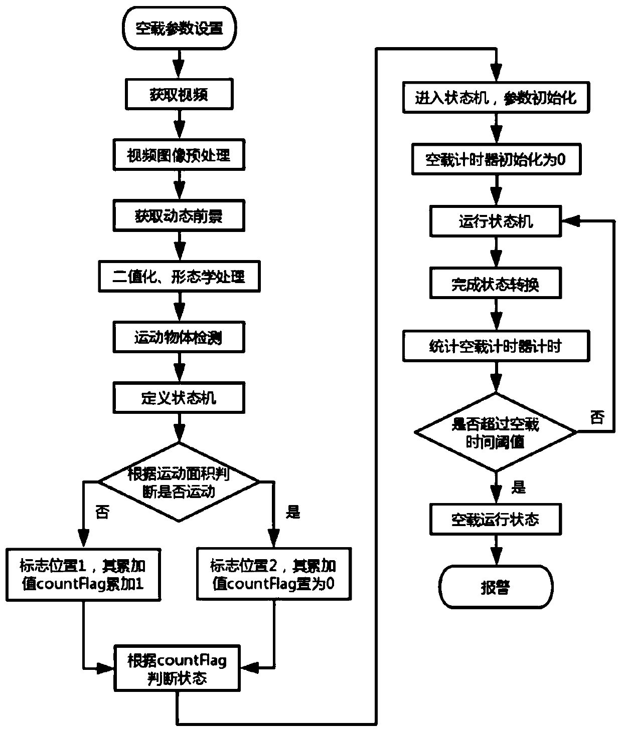
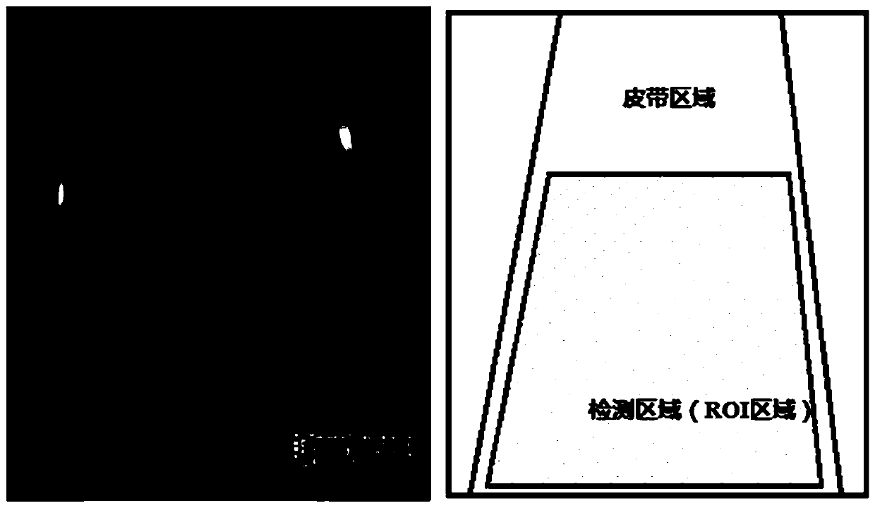
[0061] The invention proposes a video processing-based belt movement state monitoring method. The invention processes and analyzes the real-time monitoring video of the belt, judges the motion state of the belt during the carrying process, gives an alarm to the abnormal state, and can judge and distinguish the normal running state and the no-load running state of the belt. When preprocessing the video frame, use the KNN (K-Nearest, K nearest neighbor) background segmenter of the Background Subtractor (background subtraction algorithm) to set the shadow detection and obtain the dynamic foreground, thereby detecting moving objects according to the foreground area of ​​the video frame; Define a FSM (FiniteState Machine, Finite State Machine), set up flags according to the area of ​​the motion area in the video, judge the motion state of the belt in...


PUM


Abstract

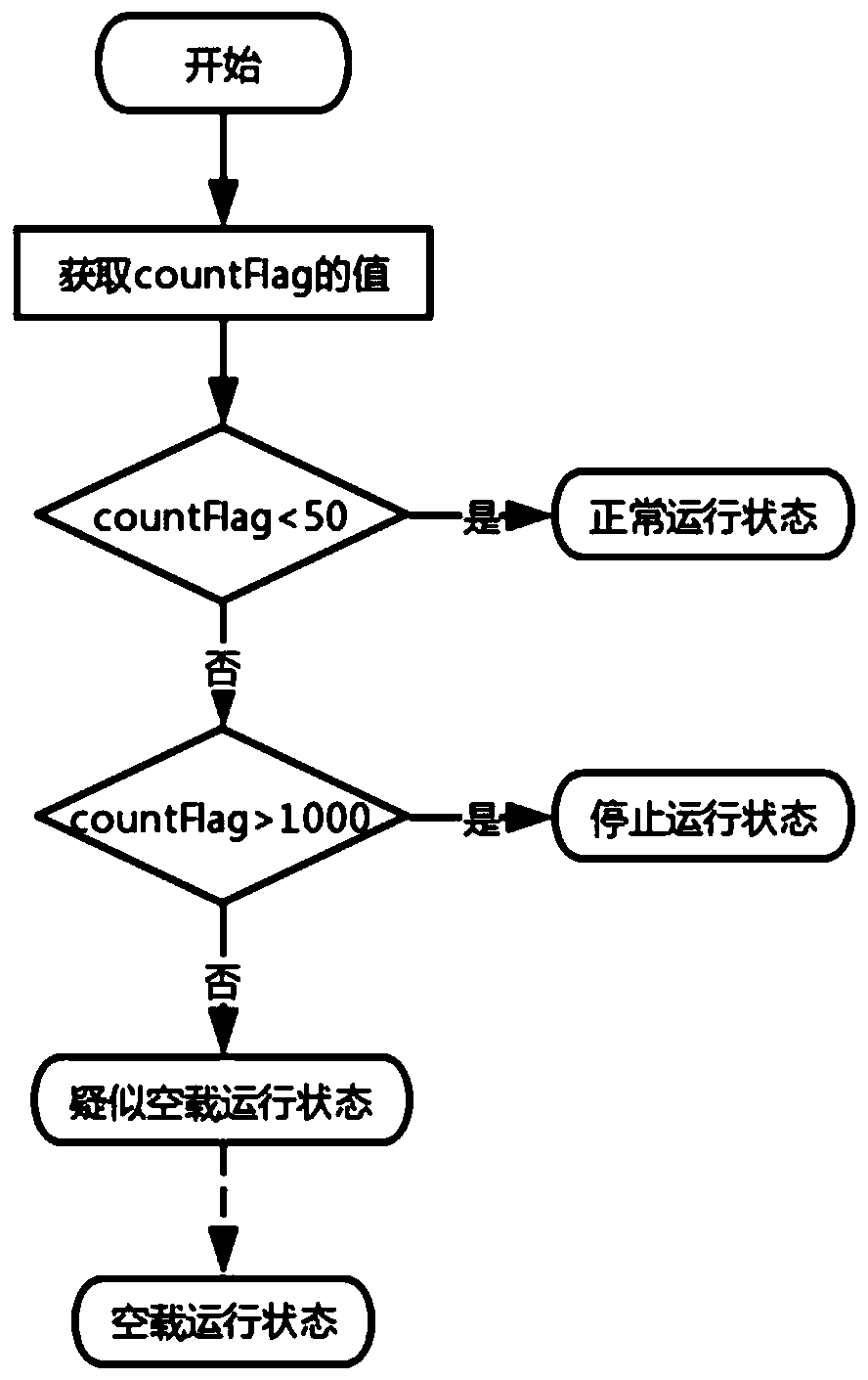
The invention discloses a belt motion state monitoring method based on video processing, and belongs to the technical field of motion detection. The method comprises the following steps: firstly, preprocessing a video, and then detecting a moving object; setting a zone bit according to the area of a motion area in the video, and judging whether the belt in the current video frame is dynamic or static; defining a state machine to realize dynamic conversion of four motion states of the belt, and then judging the state of the current video frame according to the flag bit and the accumulated valueof the flag bit, so that the motion state of the belt is judged and an alarm is given in real time. According to the invention, the non-contact detection of the belt is realized, the normal operationstate and the no-load operation state of the belt can be judged and distinguished, the support of a laser emitter and hardware equipment is not needed under the condition of ensuring the accuracy ofthe detection result, and the implementation cost of monitoring the motion state of the belt is reduced.

Description

technical field [0001] The invention belongs to the technical field of motion detection, and in particular relates to a method for monitoring the motion state of a belt based on video processing. Background technique [0002] Due to the special production conditions of coal mines, belts are important equipment for mineral material transportation, and their working status is crucial to mine safety production. The realization of intelligent mining belt movement status monitoring is of great significance for reducing labor maintenance costs and improving mining safety production. [0003] Existing belt motion state monitoring methods are generally detection methods based on hardware or video-based image processing technology. For example, in the patent CN201610970736, the logical data of belt speed and belt deviation are obtained based on ultrasonic distance measurement. Influenced by coal dust, mud, oil sludge, etc., faults such as false alarms and missed alarms are prone to...

Claims


Application Information

Patent Timeline
Patent Type & Authority Applications(China)
IPC IPC(8): H04N7/18G06T7/20
CPCG06T7/20G06T2207/10016H04N7/18
Inventor 彭延军任玉婷王元红卢新明
Owner SHANDONG UNIV OF SCI & TECH
Learn More