A kind of stump crushing method
A tree stump and drilling rig technology, applied in forestry, application, agriculture, etc., to reduce weight, improve drilling efficiency, and reduce weight
- Summary
- Abstract
- Description
- Claims
- Application Information
AI Technical Summary
Problems solved by technology
Method used
Image
Examples
Embodiment 1
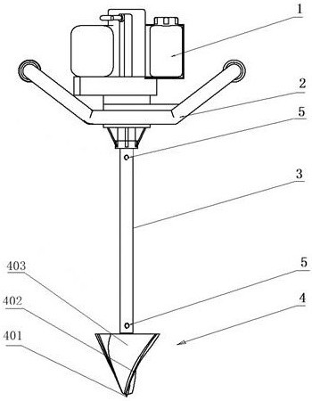
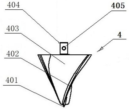
[0041] Example as Figure 1 to Figure 4 Shown: is a portable rotary drilling machine with an integral drill bit, including: a hand support 2, a power unit 1, a transmission rod 3 and an integral drill bit 4.
[0042] The hand frame 2 is a frame with a handle, and the frame of the hand frame 2 has bolt holes corresponding to the base of the power unit 1, and the power unit 1 is installed on the side of the hand frame 2 with a bolt assembly. on the frame.
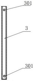
[0043] The upper end of the transmission rod 3 is detachably connected to the output shaft of the power device 1 , and the lower end of the transmission rod 3 is detachably connected to the drill bit 4 . This detachable connection can disassemble the portable rotary drilling machine into parts that are easy to carry, so that it can be transported to complex forest areas, and the diseased tree shrubs can be crushed on the spot after reassembly.
[0044] The transmission rod 3 is a round tube, preferably a round tube with a w...
Embodiment 2
[0050] Example two such as Figure 5 Shown: the difference between embodiment two and embodiment one is: embodiment one adopts integral drill bit 4, and embodiment two adopts elongated blade rotary drill bit 6.
[0051] The strip-shaped blade rotary drill bit 6 includes: a drill base body 601, a detachable conical drill bit 602, a strip-shaped blade 603, a chip removal groove 604 and a connecting pipe 606. The central axis of the top of the drill base 601 is provided with the detachable conical drill 602, and on the side of the drill base 601, there are no less than two oblong blades 603 that are evenly distributed along the side. A chip removal groove 604 is arranged between the two sets of elongated blades 603, and a circular tube-shaped connecting pipe 606 is arranged on the central axis of the bottom surface of the drill base 601, and a radial pin is arranged on the connecting pipe 606. Hole 607. The diameter of the strip-shaped blade rotary drill bit is 200 mm, and the ...
Embodiment 3
[0055] Embodiment three such as Image 6 Shown: the difference between embodiment three and embodiment one is: embodiment one adopts integral drill bit 4, and embodiment three adopts blade group rotary drill bit 7.
[0056] The blade group rotary drill bit 7 includes: a drill base body 701, a drill bit 702, a guide blade 703, a main blade 704, and a connecting pipe 706. The drill base body 701 is in the shape of a truncated cone. The drill bit 702 is provided with no less than two guide blades 703 evenly distributed along the sides on the side of the top of the drill base 701, and a plurality of helical blades 703 are arranged on the side of the drill base 701 next to the guide blades 703. Arranged main blades 704, chip removal grooves 705 are arranged between two adjacent rows of main blades 704, and a connecting pipe 706 is arranged on the central axis of the bottom surface of the drill base 701, and a radial pipe 706 is arranged on the connecting pipe 706. Pin hole 707. T...
PUM
 Abstract
Description
Claims
Application Information
 - R&D
- Intellectual Property
- Life Sciences
- Materials
- Tech Scout
- Unparalleled Data Quality
- Higher Quality Content
- 60% Fewer Hallucinations
Browse by: Latest US Patents, China's latest patents, Technical Efficacy Thesaurus, Application Domain, Technology Topic, Popular Technical Reports.
© 2025 PatSnap. All rights reserved.Legal|Privacy policy|Modern Slavery Act Transparency Statement|Sitemap|About US| Contact US: help@patsnap.com


