Fuel injection valve sleeve assembly

A technology for fuel injection valves and valve sleeves, which is applied in fuel injection devices, special fuel injection devices, and charging systems, etc., and can solve the problems of difficult processing of fuel injection valve sleeves, increased use costs, and high processing costs. Achieve mature and reliable processing technology and assembly technology, prolong service life and work reliability, and achieve the effect of precise and easy control of processing parameters

Inactive Publication Date: 2019-12-03
FAW JIEFANG AUTOMOTIVE CO
View PDF9 Cites 3 Cited by
  • Summary
  • Abstract
  • Description
  • Claims
  • Application Information

AI Technical Summary

Problems solved by technology

[0003] In the existing fuel injection valve sleeve structure, the oil outlet orifice has only one stage of throttling, that is, it only throttles once. This structure is relatively simple in processing and manufacturing, but in use, due to the weak throttling effect, the injection When the fuel flow rate is high, the risk of cavitation on the outlet end face of the oil outlet orifice is relatively high, which affects the reliability of the fuel injection valve sleeve and the entire injector, shortens its working life, and increases the cost of use.
[0004] In order to solve the above problems, in the prior art, the oil outlet orifice on the valve sleeve of the fuel injection valve is usually processed into a two-stage throttling structure, that is, the oil outlet orifice is composed of the oil outlet orifice, the diffuser area, the outlet The constriction part consists of three sections. This structure can realize two-stage throttling of high-pressure oil, reduces the flow rate of high-pressure fuel, and reduces the risk of cavitation on the outlet end face of the oil outlet orifice. However, with this oil outlet The processing and molding of the fuel injection valve sleeve of the orifice is relatively difficult, and it is difficult to accurately control the flow of the throttling parts at both ends during the processing, the scrap rate is high, and the processing cost is high

Method used


Image

  • Fuel injection valve sleeve assembly
  • Fuel injection valve sleeve assembly
  • Fuel injection valve sleeve assembly

Examples


Embodiment 1

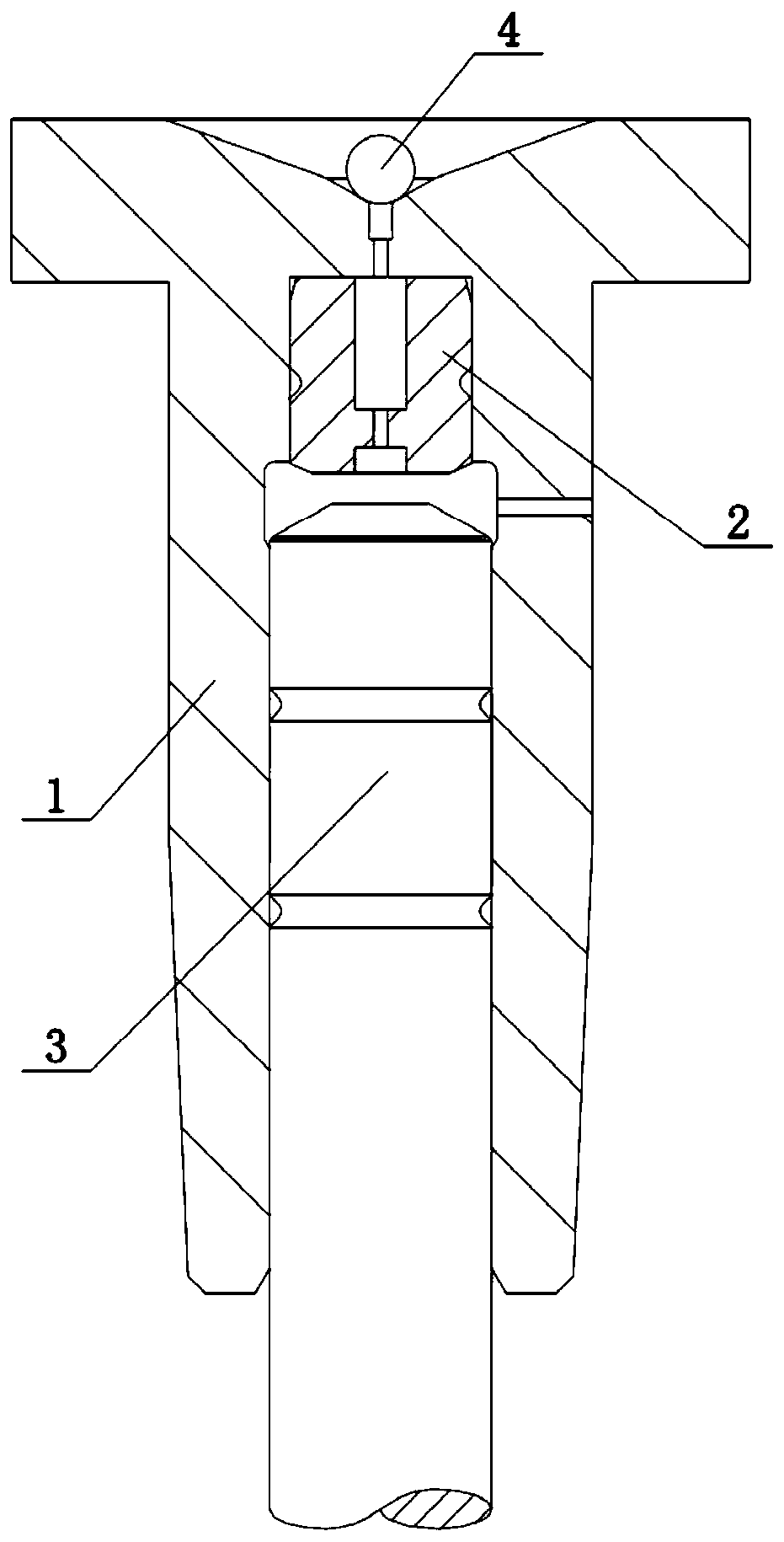
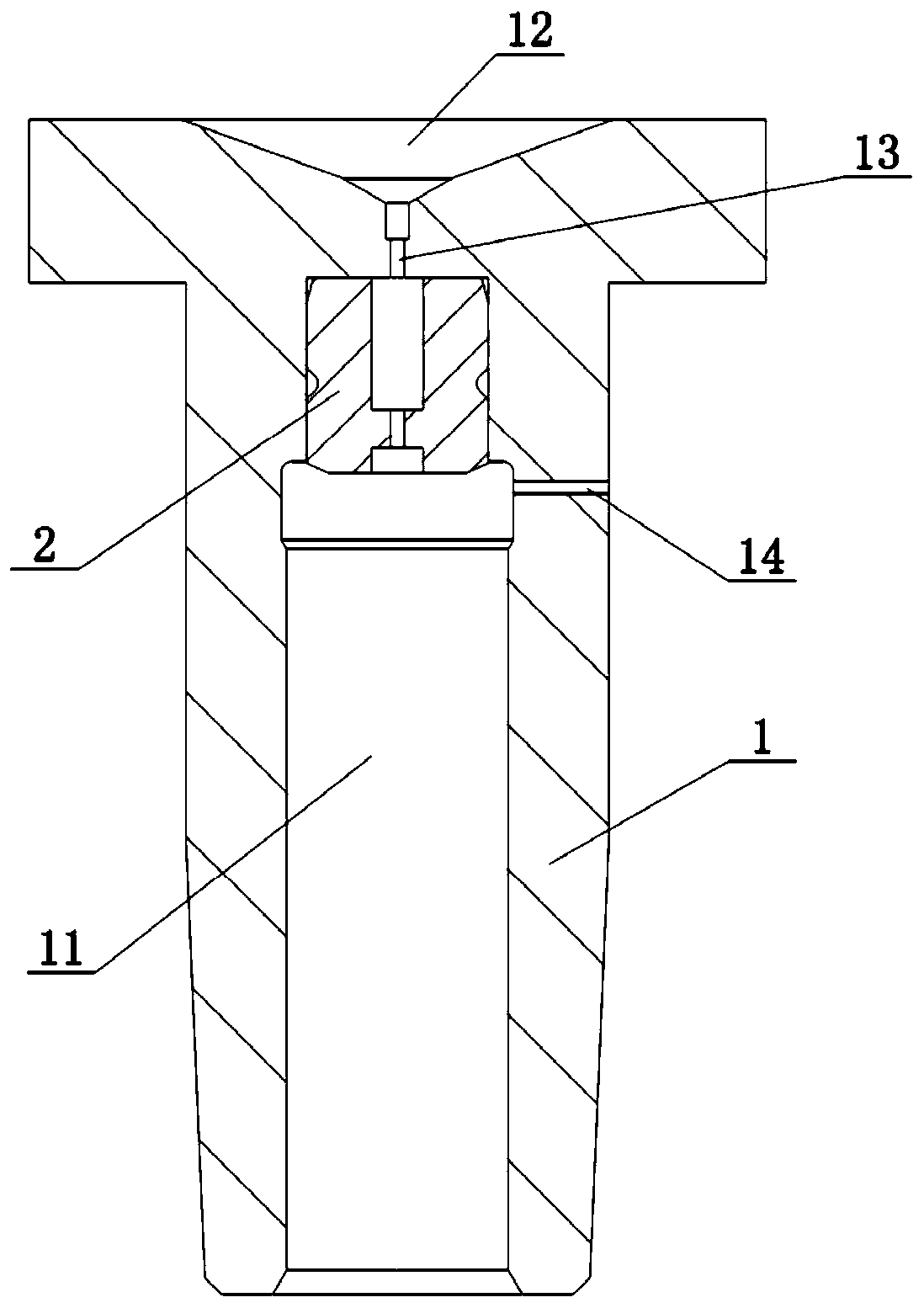
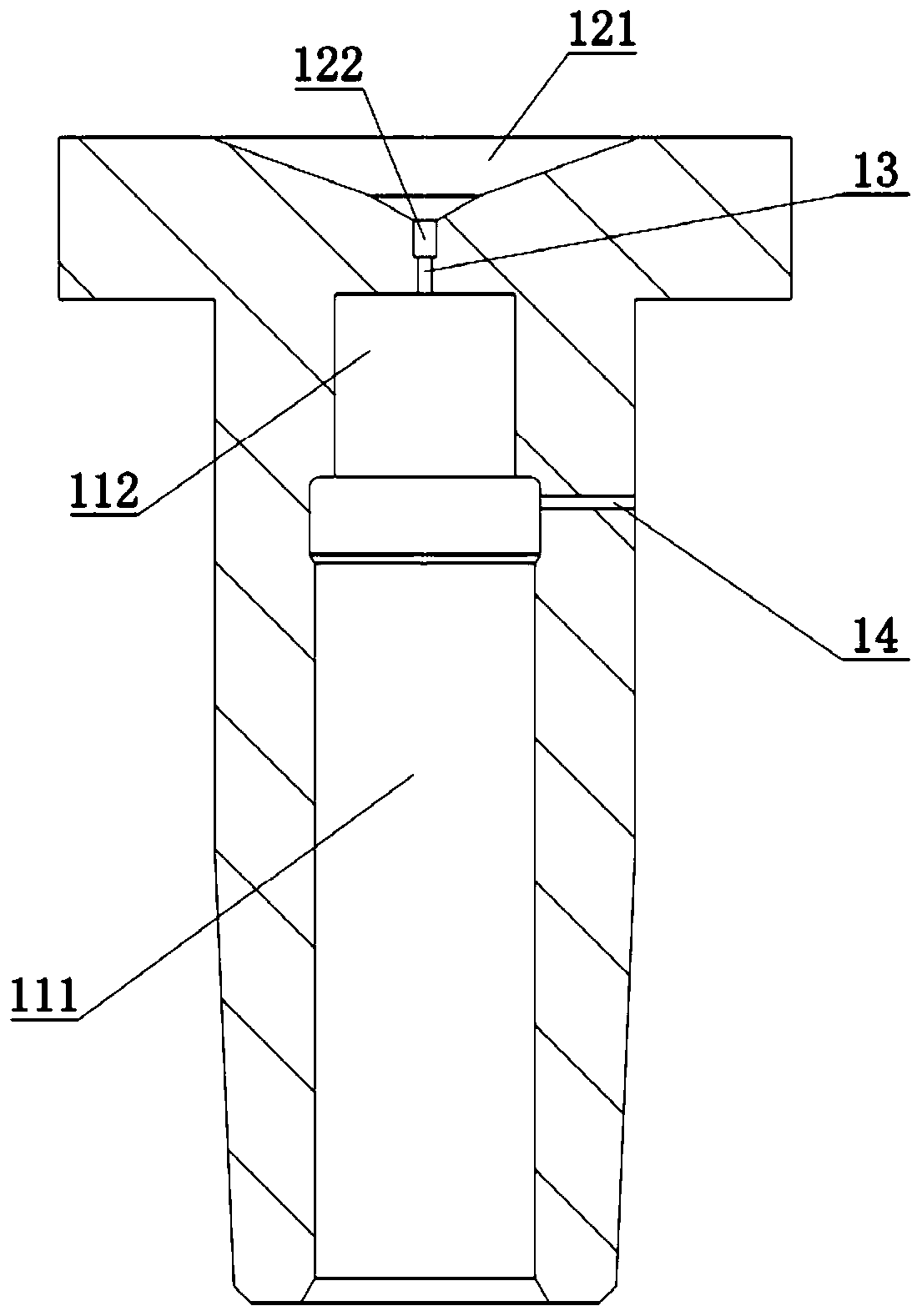
[0047] Such as Figure 1-Figure 4 As shown, this embodiment provides a fuel injection valve sleeve assembly, including a valve sleeve body 1 and a throttle sleeve 2 . Wherein, the opposite sides on the valve sleeve body 1 are respectively provided with a working groove 11 and a control groove 12, and the working groove 11 and the control groove 12 are connected through the first throttle hole 13, and the apertures of the working groove 11 and the control groove 12 are larger than The first throttle hole 13, the side wall of the operation tank 11 is provided with an oil inlet hole 14 connected to the outside, the throttle sleeve 2 is clamped on the bottom of the operation tank 11 or the control tank 12, and the throttle sleeve 2 is opposite The two sides are respectively provided with a second throttle hole 21 and an inner counterbore 22, one end of the second throttle hole 21 is located in the inner counterbore 22, and the inner counterbore 22 is connected to the first throttl...

Embodiment 2

[0057] Such as Figure 5-Figure 7 As shown, this embodiment provides a fuel injection valve sleeve assembly, which differs from Embodiment 1 in that: the throttling sleeve 2 is clamped on the bottom of the working groove 11 .

[0058] Specifically, the control groove 12 includes a control sinking groove 123 and a control clamping groove 124 arranged at the bottom of the control sinking groove 123. One end opening of the first throttle hole 13 is located in the control clamping groove 124, and the throttling sleeve 2 is interference-fitted. It is in the control card slot 124 and connected with the valve sleeve body 1 by welding.

[0059] In this embodiment, after the throttling sleeve 2 is fitted in the control slot 124 with an interference fit, the edge of the outer end surface and the contact point of the valve sleeve body 1 are fixed by welding to ensure the reliability of the throttle sleeve 2. Install to prevent high-pressure fuel from seeping into the bottom of the throt...


PUM


Abstract

The invention belongs to the technical field of fuel injectors, and discloses a fuel injection valve sleeve assembly which comprises a valve sleeve body and a throttling sleeve, wherein an operation groove and a control groove are respectively formed at two opposite sides of the valve sleeve body, the operation groove is communicated with the control groove through a first throttling hole, and anoil inlet hole communicated with the outside is formed in the side wall of the operation groove; the throttling sleeve is clamped at the bottom of the operation groove or the control groove, a secondthrottling hole and an inner side counter bore are formed at the two opposite sides of the throttling sleeve respectively, and an opening at one end of the second throttling hole is located in the inner side counter bore; the inner side counter bore is communicated with the first throttling hole, and the hole diameter of the first throttling hole and the hole diameter of the second throttling holeare both smaller than that of the inner side counter bore. According to the fuel injection valve sleeve assembly, because of the split clamping design of the valve sleeve body and the throttling sleeve, the machining and manufacturing difficulty and cost are reduced, and the secondary throttling can be achieved with lower cost.

Description

technical field [0001] The invention relates to the technical field of fuel injectors, in particular to a fuel injection valve sleeve assembly. Background technique [0002] The fuel injector is a device that injects fuel regularly and quantitatively into the combustion chamber of the engine according to the operating conditions of the engine and the working sequence of the cylinders. [0003] In the existing fuel injection valve sleeve structure, the oil outlet orifice has only one stage of throttling, that is, it only throttles once. This structure is relatively simple in processing and manufacturing, but in use, due to the weak throttling effect, the injection When the fuel flow rate is high, the risk of cavitation on the outlet end face of the oil outlet orifice is relatively high, which affects the reliability of the fuel injection valve sleeve and the entire injector, shortens its working life, and increases the use cost. [0004] In order to solve the above problems,...

Claims


Application Information

Patent Timeline
Patent Type & Authority Applications(China)
IPC IPC(8): F02M61/18F02M61/16
CPCF02M61/16F02M61/1886F02M2200/04
Inventor 喻鸣显汪祥本金昱森顾小磊王凌云王先勇缪金标张建刚栾纪杰臧娈
Owner FAW JIEFANG AUTOMOTIVE CO
Why Eureka
Try Eureka