
High-pressure-difference butterfly valve structure

A high-pressure differential and butterfly valve technology, which is applied in the direction of lifting valves, valve devices, engine components, etc., can solve the problems of reducing the service life of the valve, the valve cannot be opened normally, and the tightness of the butterfly valve is reduced, so as to prolong the service life, facilitate processing and repair Accurate control, the effect of reducing rotation wear

Inactive Publication Date: 2019-12-03
TIANJIN XIANGJIA FLUID CONTROL SYST CO LTD
View PDF10 Cites 0 Cited by
  • Summary
  • Abstract
  • Description
  • Claims
  • Application Information

AI Technical Summary

Problems solved by technology

[0003] The existing triple-eccentric butterfly valve stem does not have an adjustable limit structure. For high-pressure differential or large-diameter butterfly valves, since the ordinary valve stem and the actuator are connected by keys or gears, there is a certain gap between the connecting parts. For high-pressure differential or large-diameter butterfly valves, this makes it easy for the medium to push the butterfly plate to rotate, so that the pressure on the sealing contact surface of the valve is too high, the sealing ring is deformed, the butterfly plate passes the pass, it is difficult to open or the valve cannot be opened. It is easy to cause damage to the sealing surface, and even the valve cannot be opened normally, which reduces the service life of the valve. The valve stem rotates for a long time, which is easy to be damaged and wear to produce gaps, resulting in a decrease in the tightness of the butterfly valve.

Method used


Image

  • High-pressure-difference butterfly valve structure
  • High-pressure-difference butterfly valve structure
  • High-pressure-difference butterfly valve structure

Examples


Embodiment Construction

[0022] In order to make the purpose, technical solutions and advantages of the present invention clearer, the present invention will be further described in detail below in conjunction with the accompanying drawings. Obviously, the described embodiments are only some of the embodiments of the present invention, rather than all of them. Based on the embodiments of the present invention, all other embodiments obtained by persons of ordinary skill in the art without making creative efforts belong to the protection scope of the present invention.

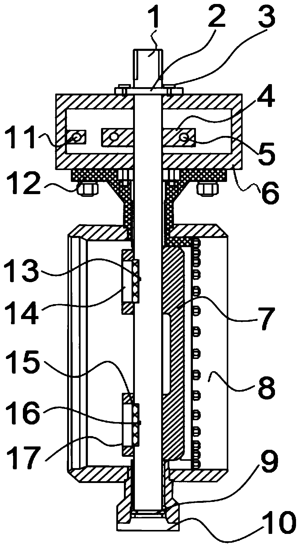
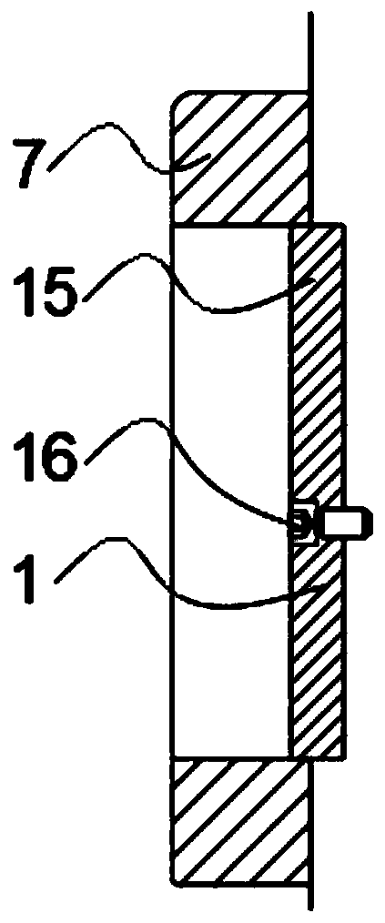
[0023] The following will combine Figure 1~Figure 4 The structure of a high pressure differential butterfly valve according to the embodiment of the present invention will be described in detail.

[0024] Such as Figure 1-4 As shown, a high-pressure differential butterfly valve structure includes a valve stem 1, a fixing device 2 and a valve body 8. The top end of the valve stem 1 is interference-connected with a fixing device 2, and...


PUM


Abstract

The invention discloses a high-pressure-difference butterfly valve structure. The invention belongs to the technical field of valves, the valve structure comprises a valve rod, a fixing device and a valve body, the top end of the valve rod is in interference connection with a fixing device; the bottom end of the fixing device is fixedly connected with a fixing plate, the bottom end of the fixing plate is in threaded connection with a fixing frame, a butterfly plate is installed on the inner side of the valve body, two key grooves are formed in the inner side of the butterfly plate, the inner side of butterfly plate is in interference connection with a key A, and the outer side of the key A is in threaded connection with a screw B. According to the invention, the rotating abrasion of the valve rod is reduced through the fixing device; a gap generated by dislocation of the butterfly plate is avoided; by adjusting the limiting screw, the limiting block is limited, and when a medium has apressure effect on the butterfly plate, the pressure of the sealing contact surface of the valve cannot be excessively increased, so that excessive closing or shrinkage deformation of the butterfly valve sealing ring is avoided, the stability of the contact pressure between the butterfly valve sealing ring and the valve seat is ensured, the service life of the sealing surface of the valve is prolonged, and the butterfly valve structure has a very good use value.

Description

technical field [0001] The invention relates to the technical field of valves, in particular to a structure of a high-pressure differential butterfly valve. Background technique [0002] The high-pressure butterfly valve is a component used to realize the on-off and flow control of the pipeline system. It has been widely used in many fields such as petroleum, chemical industry, metallurgy, hydropower, etc. According to different needs, the high-pressure butterfly valve can be used according to the structural form, sealing surface material, Sealing form, working temperature and other methods are classified. In the known butterfly valve technology, the sealing form mostly adopts the sealing structure. Due to the limitation of structural features, it is suitable for industries such as high temperature resistance, high pressure, corrosion resistance, and wear resistance. [0003] The existing triple-eccentric butterfly valve stem does not have an adjustable limit structure. For ...

Claims


Application Information

Patent Timeline
Patent Type & Authority Applications(China)
IPC IPC(8): F16K1/22F16K1/32F16K1/36F16K1/48
CPCF16K1/22F16K1/224F16K1/32F16K1/36F16K1/482
Inventor 金成波魏万春于婷婷梁爱超
Owner TIANJIN XIANGJIA FLUID CONTROL SYST CO LTD
Learn More