RFID tag

A RFID tag and tag technology, applied in the field of RFID tags, can solve problems such as not easy to kink, and achieve the effects of less trouble, good tolerance, and good conductivity

Pending Publication Date: 2019-12-03
NV BEKAERT SA
View PDF13 Cites 0 Cited by
  • Summary
  • Abstract
  • Description
  • Claims
  • Application Information

AI Technical Summary

Problems solved by technology

The 0.3mm to 0.5mm diameter multifilament structure with 49 strands has been found to be sufficiently flexible and less prone to kinks than prior art antennas

Method used


Image

  • RFID tag
  • RFID tag
  • RFID tag

Examples


Embodiment Construction

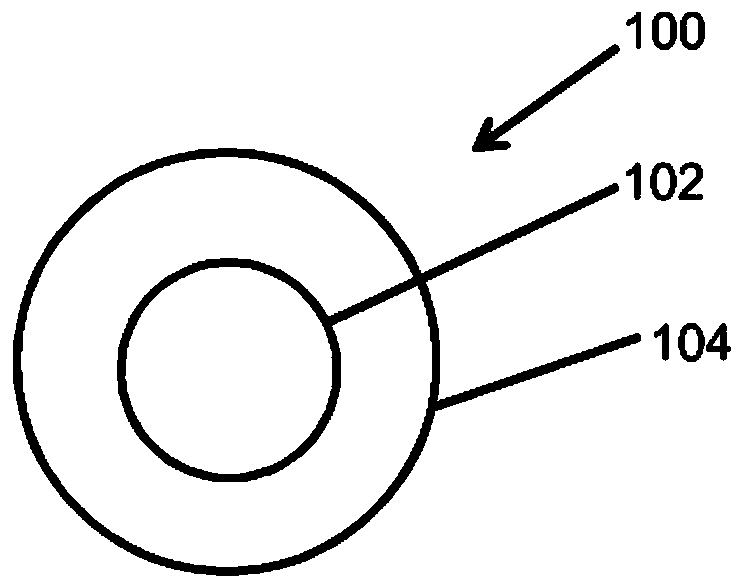
[0040] figure 1 A cross-section of a wire 100 that may be used in an antenna of an RFID tag according to the invention is shown. The wire 100 includes a core 102 made of a first metal, eg copper. The core 102 is surrounded over its entire circumference by a sheath layer 104 made of stainless steel (for example, AISI 316 stainless steel). In this example, the cross-section of the wire 100 is circular; the core 102 has a circular cross-section, which is arranged concentrically with the cross-section of the wire 100 . As an example, the wire has a diameter of 100 μm, wherein the core made of copper has a diameter of 60 μm. Thus, in the cross-section of the wire, the ratio of the area of ​​the core to the area of ​​the layer made of stainless steel is 0.56.

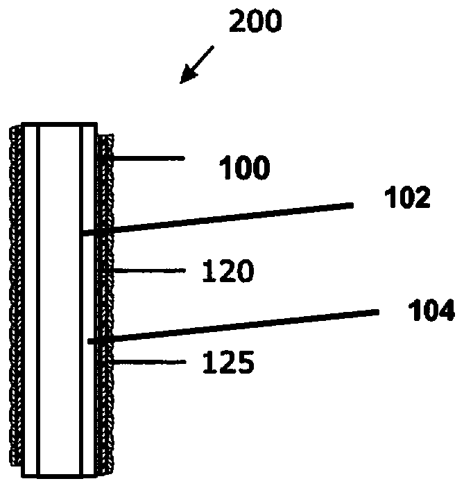
[0041] figure 2 A section 200 in a plane passing through and along the axis of an exemplary antenna for an RFID tag according to the first aspect of the present invention is shown. Exemplary RFID antennas have been used...


PUM

PropertyMeasurementUnit
Diameteraaaaaaaaaa
Diameteraaaaaaaaaa

Abstract

The RFID tag comprises a transponder chip and an antenna. The antenna is coupled to the transponder chip. The antenna comprises a metal wire or a strand of metal wires. The metal wire(s) comprise(s) acore-sheath structure. The metal wire or the metal wires comprise(s) a core out of a first metal; and a sheath layer. The core is over its full circumference surrounded by the sheath layer out of stainless steel. The first metal has electrical conductivity higher than stainless steel.

Description

technical field [0001] The present invention relates to the field of RFID tags. Background technique [0002] WO2014 / 204322A1 discloses an RFID tag which is particularly suitable as a linen or clothing tag. In a particular embodiment, an RFID tag includes a backing layer, a first adhesive layer covering the backing layer, an RFID transponder and antenna covering the first adhesive layer, and a second adhesive covering the RFID transponder and antenna. mixture layer. These layers are laminated together to hermetically seal the RFID transponder and antenna within the RFID tag. In a preferred embodiment, the antenna comprises an elongated multi-strand stainless steel wire, for example, having 49 strands. Preferably, the wires are between 0.3mm and 0.5mm in diameter and are encapsulated in nylon or other polymer insulation. This multifilament structure with 49 strands and a diameter of 0.3 mm to 0.5 mm has been found to be sufficiently flexible and less prone to kinks than p...

Claims


Application Information

Patent Timeline
IPC IPC(8): G06K19/077H01B1/00
CPCG06K19/077G06K19/027G06K19/07749G06K19/07773
Inventor G·德罗萨尔特R·梅斯
Owner NV BEKAERT SA
Why Eureka
Try Eureka