Invisible appliance production method

An invisible appliance and production method technology, applied in medical science, dentistry, laser welding equipment, etc., can solve the problems of affecting the patient's wearing and orthodontic effect, and the smoke and dust are unfavorable to the quality of the appliance, so as to reduce subsequent quality defects and have a beautiful appearance. , The effect of improving product yield

Pending Publication Date: 2019-12-06
浙江正雅齿科股份有限公司
View PDF6 Cites 6 Cited by
  • Summary
  • Abstract
  • Description
  • Claims
  • Application Information

AI Technical Summary

Problems solved by technology

[0005] The main purpose of the present invention is to overcome the defects of the prior art, provide a production method for invisible aligners, and solve the problem that the smoke and dust produced in the laser cutting process of the production of the existing invisible aligners have an adverse effect on the quality of the aligners, thereby affecting the wearing of the patients and treatment effects

Method used


Image

  • Invisible appliance production method
  • Invisible appliance production method
  • Invisible appliance production method

Examples


Embodiment 1

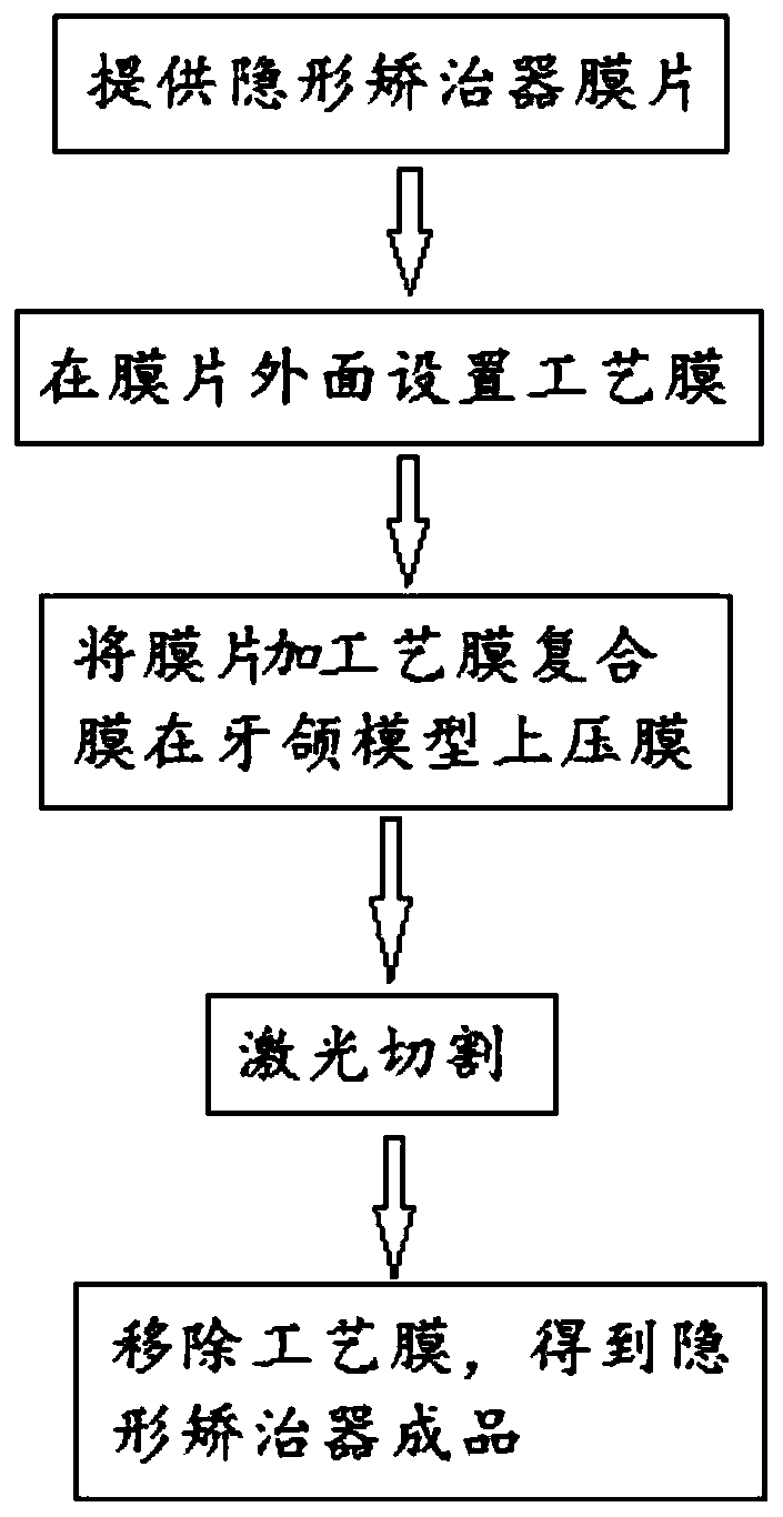
[0054] See image 3 , the invisible aligner production method of the present embodiment comprises the following steps:

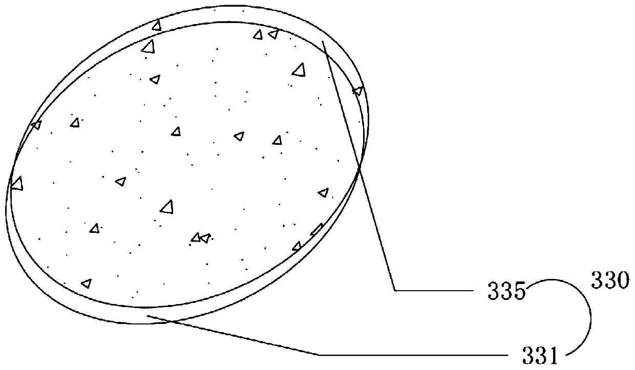
[0055] Provide a diaphragm 331 for making invisible aligners; provide a process film 335;

[0056] A layer of process film 335 is set on the outer surface of the diaphragm 331 to obtain a diaphragm composite film 330; in the diaphragm composite film, the process film 335 is substantially equal in size to the diaphragm 331, and the process film 335 can cover the position of the cutting path The film at the place; specifically, the process film 335 and the film 331 are combined in a rolling manner, and in an alternative embodiment, the process film 335 and the film 331 can also be pasted, Electrostatic or hot pressing mode combination; Specifically, the specific operation mode of process film being arranged on the diaphragm can be to cover the continuous process film 335 on the continuous diaphragm 331 first, and then obtain the circular composite film 330 by...

Embodiment 2

[0065] See Figure 4 , the invisible aligner production method of the present embodiment comprises the following steps:

[0066] Provide a diaphragm 431 for making invisible aligners; provide a process film 435; the size of the process film 435 is smaller than the diaphragm 431;

[0067] A layer of process film 435 is set on the outer surface of the diaphragm 431 to obtain a diaphragm composite film 430; in this embodiment, the process film 435 is combined with the diaphragm 431 in a sticky manner In an embodiment, the process film 435 and the diaphragm 431 can also be combined by static electricity, extrusion, hot pressing, etc.; the process film 435 can cover the diaphragm at the position of the cutting path; specifically, it can be continuous The process film 435 is arranged on the continuous film sheet 431, and then cut to obtain Figure 4 The disc-shaped diaphragm composite membrane 430 shown in ; or it can also be that the circular diaphragm 431 and the process film 43...

Embodiment 3

[0076] See Figure 5 , the invisible aligner production method of the present embodiment comprises the following steps:

[0077] Provide a diaphragm 531 for making invisible aligners; provide a process film 535; the size of the process film 535 is smaller than the diaphragm 531, and is U-shaped;

[0078] A layer of process film 535 is set on the outer surface of the diaphragm 531 to obtain a diaphragm composite film 530; in this embodiment, the process film 535 is electrostatically combined with the diaphragm 531, and in addition In an embodiment, the process film 535 and the diaphragm 531 can also be combined by pasting, extrusion, hot pressing, etc.; the process film 535 can cover the diaphragm at the position of the cutting path, but the process film 535 It does not cover the part of the film 531 other than the position of the invisible aligner; specifically, the process film 535 can be continuously placed on the continuous film 531 first, and then cut to obtain Figure 5...


PUM

PropertyMeasurementUnit
thicknessaaaaaaaaaa
thicknessaaaaaaaaaa
thicknessaaaaaaaaaa

Abstract

The invention relates to the technical field of dental orthodontics, and specifically discloses an invisible appliance production method. The invisible appliance production method comprises the following steps of: providing a diaphragm for making an invisible appliance; arranging a layer of process film on the outer surface of the diaphragm; placing the diaphragm and one surface opposite to the outer surface provided with the process film on a dental model for film pressing to obtain the invisible appliance to be cut; performing laser cutting on the invisible appliance to be cut along a predetermined cutting path, wherein laser is incident from one side of the process film, the laser cuts through the process film and the diaphragm simultaneously, and the diaphragm and the process film arenot mixed at the cutting path; and removing the process film to obtain the invisible appliance. The invisible appliance production method solves the adverse effect on the quality of the appliance caused by smoke dust generated in the laser cutting process of the existing invisible appliance production.

Description

technical field [0001] The invention belongs to the field of preparation of dental appliances, more precisely relates to the manufacturing technology of invisible appliances, and in particular relates to a method for eliminating smoke and dust adhering to invisible appliances during laser cutting in the laser cutting process. Background technique [0002] Invisible aligners are being used more and more widely in the orthodontic industry, and their transparent effect and easy-to-wear usage are favored by more and more doctors and patients. [0003] The manufacturing process of the invisible aligner is mainly to obtain the digital intraoral model of the patient first, then perform incisor and tooth arrangement on the digital intraoral model of the patient, simulate the orthodontic process step by step, and then manufacture the step by step tooth model through 3D printing technology. Then use polymer materials to heat and press the film, and obtain a set of invisible aligners w...

Claims


Application Information

Patent Timeline
Patent Type & Authority Applications(China)
IPC IPC(8): B29C51/26B23K26/38A61C7/00
CPCA61C7/00B23K26/38B29C51/264B29C51/268
Inventor 姚峻峰刘喆威
Owner 浙江正雅齿科股份有限公司
Why Eureka
Try Eureka