Circulating fluid system for electrostatic adsorption chuck

A technology of electrostatic adsorption and circulating fluid, which is applied in the field of circulating fluid system, can solve the problems affecting the service life of the cooler and the efficiency of the machine, and achieve the effect of avoiding excessive heating power and shortening the heating and cooling time

Inactive Publication Date: 2019-12-06
BEIJING NAURA MICROELECTRONICS EQUIP CO LTD
View PDF10 Cites 5 Cited by
  • Summary
  • Abstract
  • Description
  • Claims
  • Application Information

AI Technical Summary

Problems solved by technology

When the chamber has finished running the low-temperature process and needs to perform high-temperature process, the ESC needs to wait for 16 minutes to reduce the temperature to the required time. The long time of temperature change seriously affects the efficiency of the machine, and the frequent heating and cooling of the cooler will affect the use of the cooler. life

Method used


Image

  • Circulating fluid system for electrostatic adsorption chuck
  • Circulating fluid system for electrostatic adsorption chuck
  • Circulating fluid system for electrostatic adsorption chuck

Examples


no. 1 example

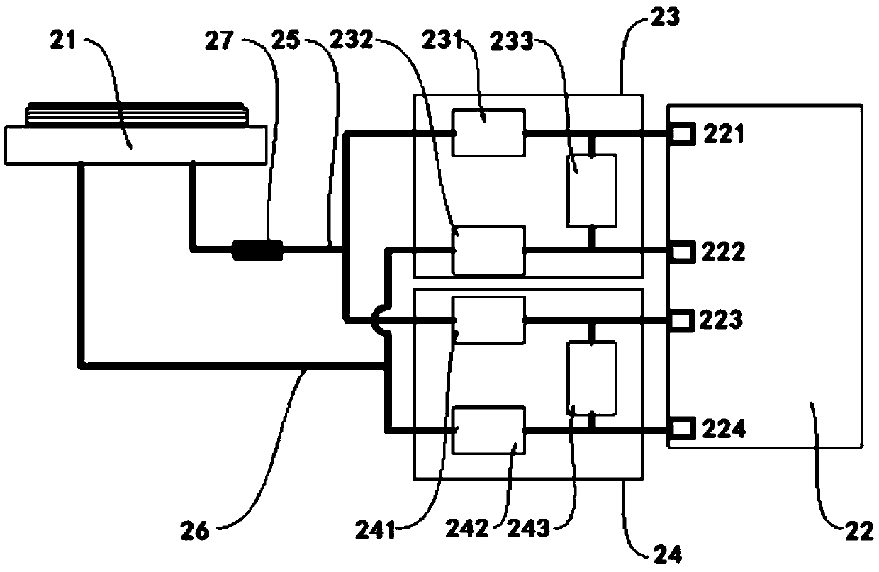
[0034] figure 2 A structural diagram of the circulating fluid system of the electrostatic adsorption chuck according to the first embodiment of the present invention is shown. The base body of the electrostatic adsorption chuck contains a cooling fluid circulation channel (not shown).

[0035] Such as figure 2As shown, the circulating fluid system includes a cooling machine 22 connected to the cooling fluid circulating waterway in the electrostatic adsorption chuck 21 . The cooling machine 22 is configured to be able to pump out the first circulating fluid and the second circulating fluid at different temperatures at the same time, when one circulating fluid circulates through the cooling fluid circulating water circuit, the other circulating fluid is outside the electrostatic adsorption chuck cycle.

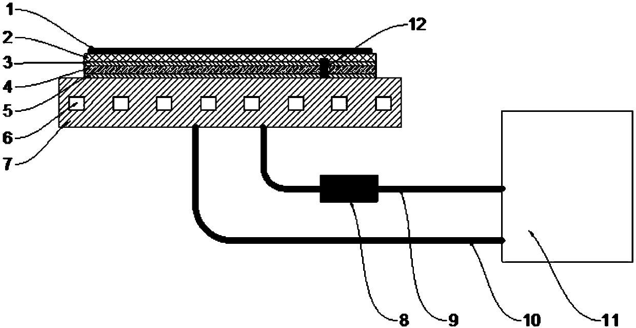
[0036] Electrostatic adsorption chuck 21 can adopt figure 1 structure shown. The temperature of the first circulating liquid and the second circulating liquid can be set a...

no. 2 example

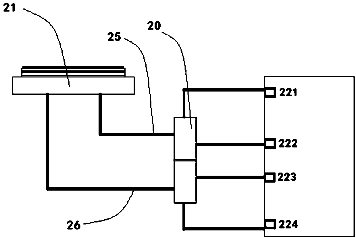
[0056] image 3 A configuration diagram showing a circulating liquid system of an electrostatic adsorption chuck according to a second embodiment of the present invention. In this embodiment, the structures of the electrostatic adsorption chuck 21 and the cooling machine 22 are the same as those in the first embodiment, and the cooling machine 22 is configured to be able to simultaneously pump out the first circulating fluid and the second circulating fluid of different temperatures, one of which When the circulating fluid circulates through the cooling fluid circulation channel in the electrostatic adsorption chuck 21 , another circulating fluid circulates outside the electrostatic adsorption chuck.

[0057] In this embodiment, the circulating fluid system further includes a flow switching device 20 . The first circulating fluid outlet 221, the first circulating fluid inlet 222, the second circulating fluid outlet 223 and the second circulating fluid inlet 224 of the cooling...


PUM


Abstract

The invention discloses a circulating fluid system for an electrostatic adsorption chuck. The base body of the electrostatic adsorption chuck contains a cooling liquid circulating water path. The circulating fluid system includes a cooler connected to the cooling liquid circulating water path, and the cooler is configured to be capable of simultaneously pumping a first circulating fluid and a second circulating fluid having different temperatures, wherein when one of the circulating fluids circulates through the cooling liquid circulating water path, the other circulating liquid circulates outside the electrostatic adsorption chuck. By introducing a dual-channel cooler with two independent circulating liquids of two temperatures, the temperature-stabilizing circulating liquids entering thebase body of the electrostatic adsorption chuck can be switched between the circulating liquids of two temperatures, which shortens the circulating liquid temperature increasing and decreasing time between high and low temperature processes, achieving rapid temperature control of the electrostatic adsorption chuck in different temperature processes, and avoiding damage to the electrostatic adsorption chuck due to excessive heating power of the electrostatic adsorption chuck.

Description

technical field [0001] The invention relates to the field of semiconductor integrated circuit manufacturing, in particular to a circulating liquid system for an electrostatic adsorption chuck. Background technique [0002] The present invention relates to semiconductor manufacturing equipment. In the manufacturing process of IC (integrated circuit), etching machine is an indispensable equipment, wherein ESC (electrostatic adsorption chuck) is to provide wafer (wafer) with the temperature required for the process. As a key component, the quality of a finished wafer is inseparable from the stability and uniformity of the ESC temperature during the process. [0003] ESC stabilizes the temperature at the desired value through the circulating fluid inside the substrate and its own electric heating layer. With the continuous development of the semiconductor industry and the birth of the updated process, the requirements for the etching process and efficiency are getting higher an...

Claims


Application Information

Patent Timeline
Patent Type & Authority Applications(China)
IPC IPC(8): H01L21/683
CPCH01L21/6831H01L21/6833
Inventor 马恩泽楼丰瑞石锗元
Owner BEIJING NAURA MICROELECTRONICS EQUIP CO LTD
Why Eureka
Try Eureka