
Device and method for hot embossing of a polymer layer

a polymer layer and polymer layer technology, applied in the field of hot embossing of polymer layers and hot embossing of magnetic nanoparticlecontaining polymer layers, can solve the problems of shortening the thermal cycle, external cooling of the substrate after the embossing process, and other disadvantages, so as to achieve optimized throughput and reduce energy consumption.

Active Publication Date: 2014-06-03
EV GRP E THALLNER GMBH
View PDF19 Cites 2 Cited by
  • Summary
  • Abstract
  • Description
  • Claims
  • Application Information

AI Technical Summary

Benefits of technology

[0006]The object of the invention is therefore to devise a device and a method for hot embossing of a polymer layer onto a substrate in which the throughput is optimized and energy use is reduced.
[0008]The invention is based on the idea of devising a device with a thermal mass which has been reduced to a minimum, so that heating and cooling times in hot embossing can be shortened as effectively as possible. For this purpose, as claimed in the invention there is a temperature raising device, especially a magnetic field generating device, which is made specifically to heat up the polymer layer. This drastically reduces the thermal inertia of the device as claimed in the invention.
[0010]The object is achieved especially in that the thermal mass of the hot embossing device is reduced to the mass of the polymer layer to be embossed, and the temperature of the polymer layer penetrated with magnetic nanoparticles is raised by exposing the magnetic nanoparticles to a preferably high frequency alternating magnetic field. In this way, in contrast to conventional hot embossing methods, only the polymer layer to be embossed or parts of the polymer layer to be embossed are heated to the necessary embossing temperature and heating or cooling of the entire hot embossing device is eliminated. In one advantageous configuration of the invention it is provided that the magnetic field generating means is made to produce an especially high frequency alternating magnetic field which is homogeneous preferably at least in the region of the polymer layer. The homogeneous alternating magnetic field uniformly heats the polymer layer without distortions or uneven softening occurring.
[0011]Advantageously there is an application means for applying a polymer layer to the substrate, especially integrated into the device so that application of the polymer layer can take place within the device and in this way the throughput is further increased. The substrate can be a wafer. The polymer layer is applied in a spin, spray or inkjet method.
[0018]After completed pressure application, the polymer layer is cooled; this takes place within an extremely short time by the heating which has advantageously taken place intrinsically, since the other components of the device were not heated at all or were heated only insignificantly. Below the softening point of the polymer layer the embossing die is separated from the polymer layer which has at least partially set.

Problems solved by technology

Different approaches such as shortening of thermal cycles, for example by use of polymers with low glass transition temperature, or the external cooling of the substrate after the embossing process have not shown the desired effects or have entailed other disadvantages.

Method used


Image

  • Device and method for hot embossing of a polymer layer
  • Device and method for hot embossing of a polymer layer
  • Device and method for hot embossing of a polymer layer

Examples


Embodiment Construction

[0023]The same components and components with the same function are identified with the same reference numbers in the figures.

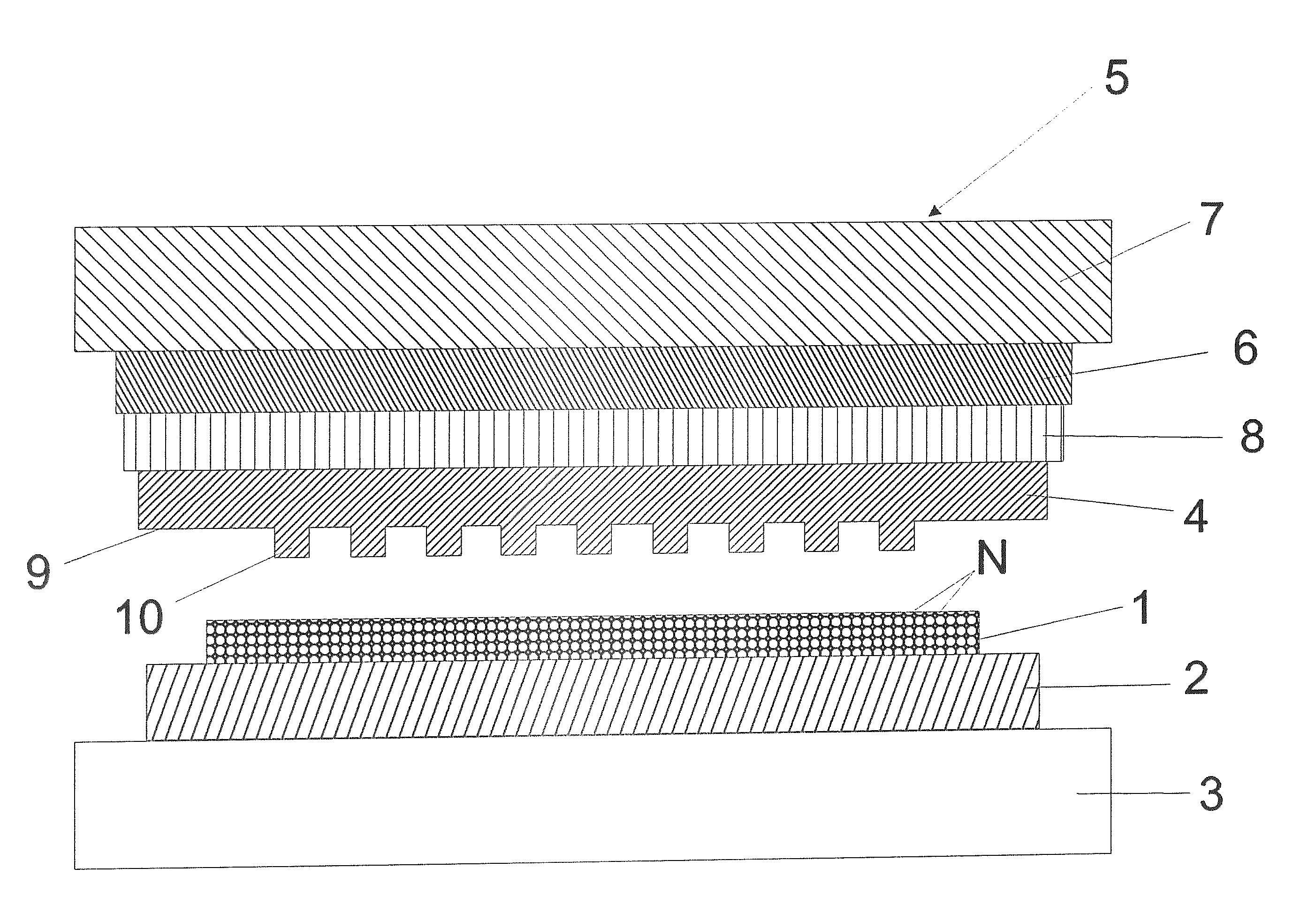
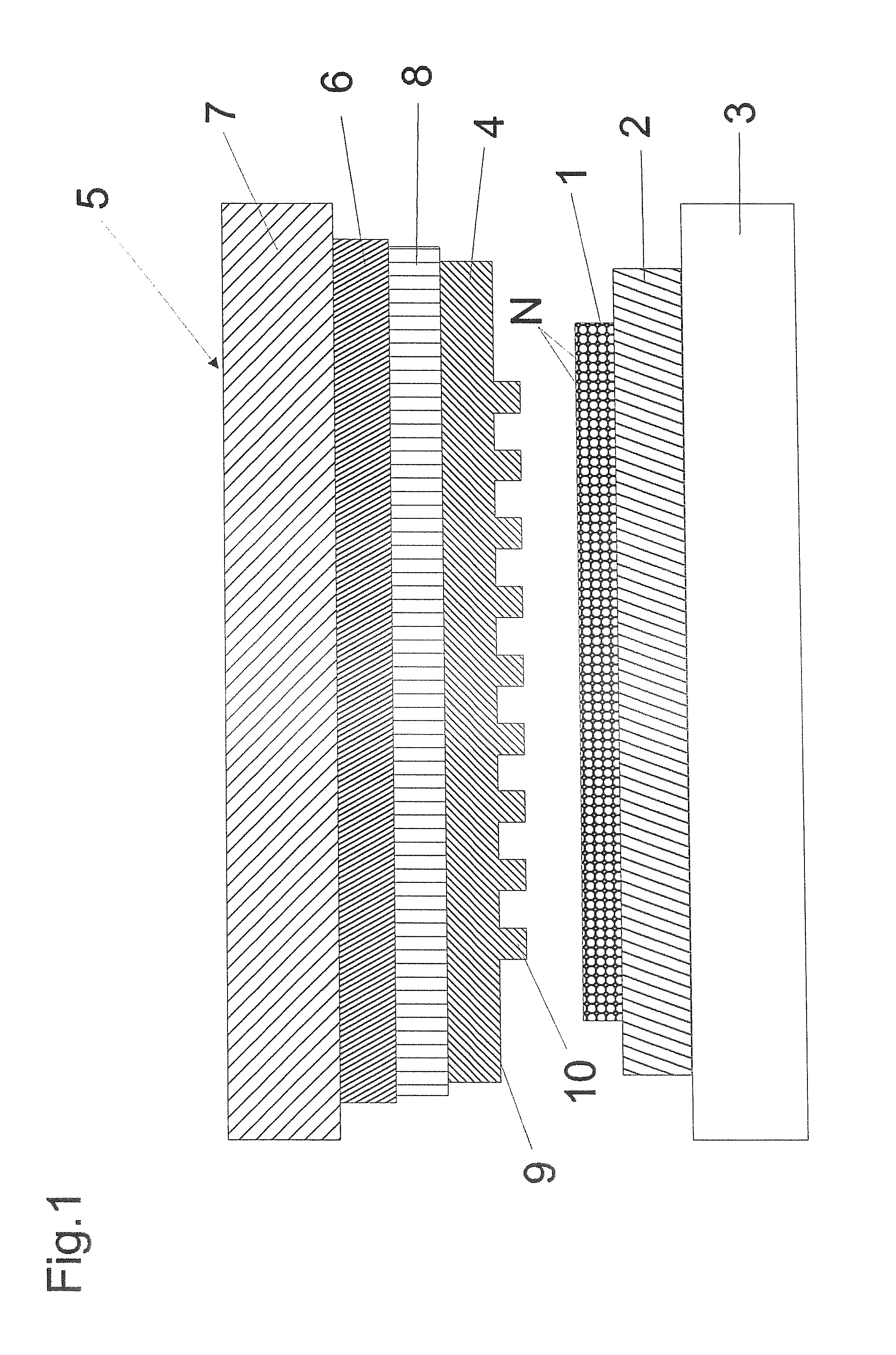
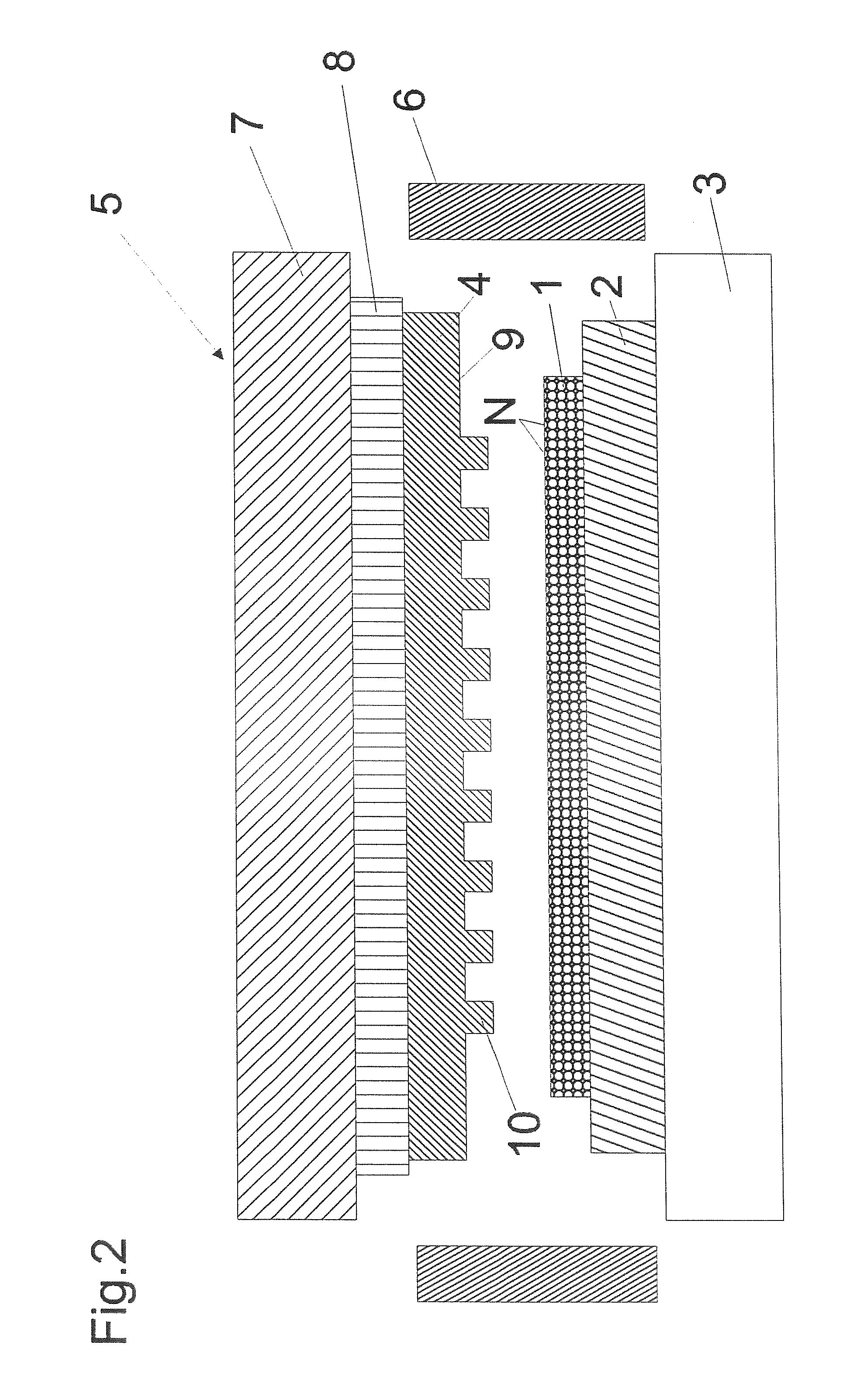
[0024]FIG. 1 shows a substrate 2 which is to be provided with a polymer layer 1 on a substrate holder 3. The substrate holder 3 can be a chuck and the substrate 2 is applied to the substrate holder 3 by a robot arm which is not shown and is unloaded again after application of the polymer layer 1.

[0025]The polymer layer 1 contains magnetic nanoparticles N which are distributed as uniformly as possible in the polymer layer 1.

[0026]The polymer layer 1 is applied or placed for example by spin lacquering, lamination or joining to the substrate during embossing or by inkjet methods.

[0027]Opposite the substrate holder 3 a pressure application means 5 is fixed on the device and the pressure application means 5 has a pressure cylinder 7 which can move an embossing die 4 which is attached to the pressure cylinder 7 in the direction of the substrate 2. The embossing die...


PUM

PropertyMeasurementUnit
particle sizeaaaaaaaaaa

Abstract

The invention relates to a device for hot embossing of a magnetic nanoparticle (N)-containing polymer layer and a method for hot embossing of a magnetic nanoparticle-containing polymer layer.

Description

FIELD OF THE INVENTION[0001]The invention relates to a device for hot embossing of a polymer layer and a method for hot embossing of a magnetic nanoparticle-containing polymer layer.BACKGROUND OF THE INVENTION[0002]In micro- and nanoengineering, hot embossing is used for transfer of a microscale or nanoscale pattern into a polymer layer. Here a flat substrate is first coated with a polymer and then is brought into contact with a prestructured die. Then the polymer is heated to liquefy it. The die is then pressed into the liquid polymer layer at a defined pressure. It is especially important to apply an embossing pressure which is as uniform as possible over the entire surface of the substrate. Then the polymer layer is molded by the die at a predefined temperature and cooled to room temperature.[0003]Hot embossing is used among others for producing micro-optical structures, microfluidic components and magnetic data media.[0004]Compared to photolithographic methods, the throughput fo...

Claims


Application Information

Patent Timeline
Patent Type & Authority Patents(United States)
IPC IPC(8): B29C59/02H05B6/02B28B1/00
CPCB29C35/0272B29C59/02B29C59/022B82Y40/00B29C2059/023B29L2031/7562B82Y10/00B29C35/0288G03F7/0002
Inventor KAST, MICHAEL
Owner EV GRP E THALLNER GMBH
Learn More