Profile modeling prefabricated part puncture method

A prefabricated part and reverse direction technology, which is applied in the field of aerospace prefabricated parts preparation, can solve the problem of low puncture efficiency

Inactive Publication Date: 2019-12-10
CHANGSHA JINGYOU NEW MATERIAL TECH CO LTD
View PDF8 Cites 4 Cited by
  • Summary
  • Abstract
  • Description
  • Claims
  • Application Information

AI Technical Summary

Problems solved by technology

[0003] The invention provides a puncture method for profiling prefabricated parts, which is used to overcome the defects of low puncture efficiency in the prior art and realize

Method used


Image

  • Profile modeling prefabricated part puncture method
  • Profile modeling prefabricated part puncture method
  • Profile modeling prefabricated part puncture method

Examples


Embodiment 1

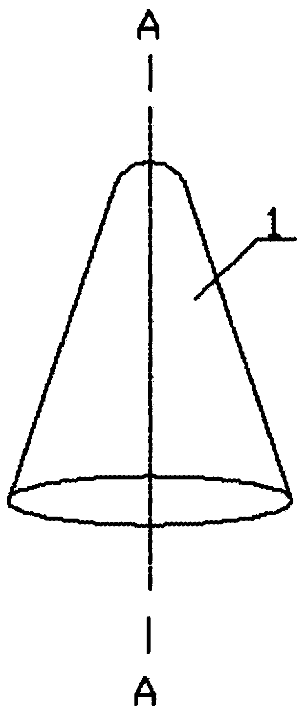
[0021] as attached figure 1 Shown, a kind of profiling preform 1 piercing method comprises the following steps:

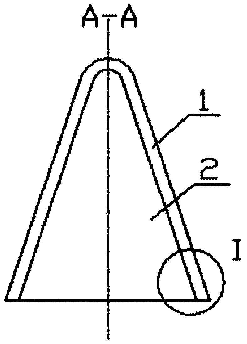
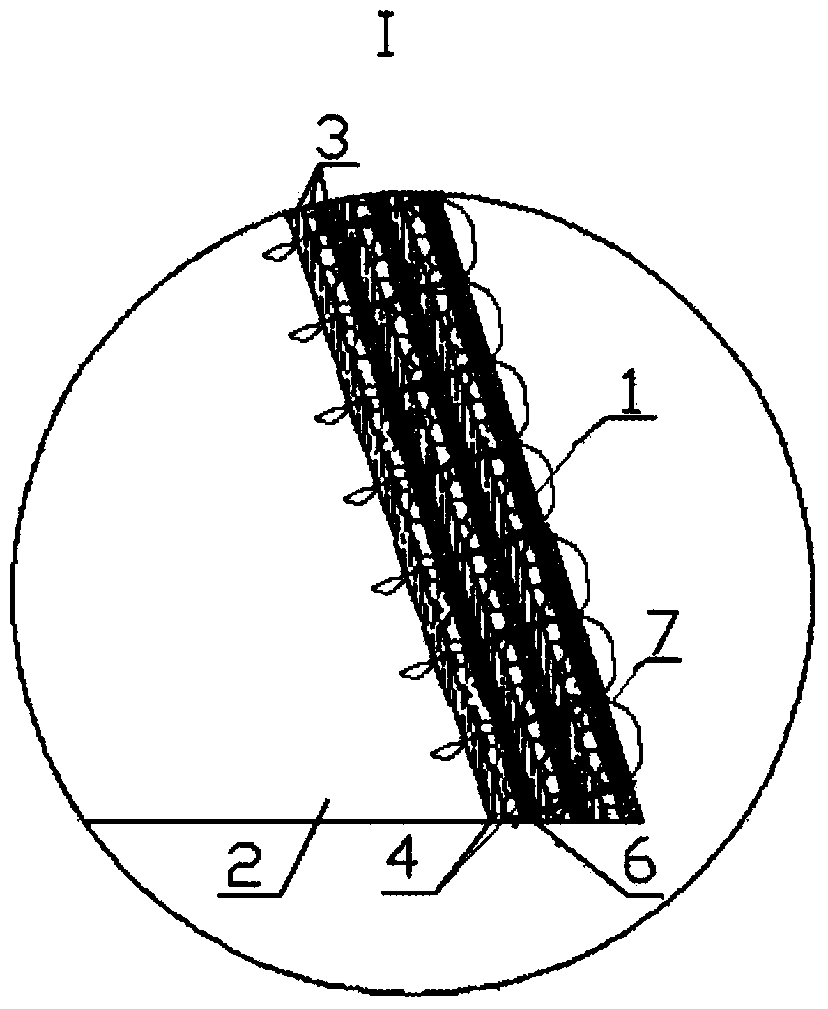
[0022] S1, wrapping the multi-layer fiber cloth 4 on the mold 2, and sewing the multi-layer fiber cloth along the joint of the fiber cloth to form a laminated unit 3;

[0023] Generally, a three-layer fiber cloth layer 4 is used as a laminated unit 3; the fiber cloth here is formed by weaving longitudinally and horizontally with warp fibers and weft fibers. The size of the fiber cloth is selected according to the raw materials used, and the fiber cloth is laid along the outer surface of the mold. Or wrap multiple layers around the mold, a piece of fiber cloth can wrap 1 to 3 layers around the mold, or any non-integer layer, and the laying of a laminated unit is completed by laying multiple pieces of fiber cloth multiple times.

[0024] When laying multiple times, the multi-layer fiber cloth is wrapped on the mold, and each layer of fiber cloth can be sewed along t...

Embodiment 2

[0039] Preferably, the step S2 of repeating the above step S1 to form a plurality of laminated units, and sewing all the laminated units to form a semi-finished product includes:

[0040] S21A wrapping three layers of fiber cloth on the lamination unit, and the joints of the fiber cloth are interlaced with each other during the wrapping process;

[0041] S22A Sew three layers of fiber and all layers of fiber cloth of the previous stacked unit along the joint position of the fiber cloth to complete the stitching of two adjacent stacked units;

[0042] S23A repeats the above wrapping step S21A and sewing step S22A, and sequentially completes the sewing of two adjacent stacked units from the inside to the outside; here, the inside refers to the direction close to the mold, and the outside refers to the direction away from the mold;

[0043] After S24A is demolded, all laminated units are stitched through to form a semi-finished product.

[0044] In this scheme, the first stackin...

Embodiment 3

[0046] Preferably, the step S2 of repeating the above step S1 to form a plurality of laminated units, and sewing all the laminated units to form a semi-finished product further includes:

[0047] S21B wrapping two layers of fiber cloth on the lamination unit, and the joints of the fiber cloth are interlaced with each other during the wrapping process;

[0048] S22B sets a fiber net sleeve on two layers of fiber cloth;

[0049] S23B Sew two layers of fiber, fiber net cover layer and upper layer of unit cloth along the joint position of fiber cloth to complete the stitching of adjacent two layers of units;

[0050] S24B ​​repeats the above wrapping steps S21B, S22B and sewing step S23B, and sequentially completes the sewing of two adjacent stacked units from inside to outside;

[0051] After the S25B is demoulded, all laminated units are stitched through to form a semi-finished product.

[0052] In this scheme, the first stacking unit, the second stacking unit, the third stack...


PUM


Abstract

The invention discloses a profile modeling prefabricated part puncture method. The profile modeling prefabricated part puncture method includes the following steps that a mould is wrapped with multilayer fibre cloths, the multilayer fibre cloths are sutured in a penetrating mode along joints of the fibre cloths, and a cascading unit is formed; the step is repeated to form a plurality of cascadingunits, and a semi-finished product is formed by suturing all the cascading units in a penetrating mode, a hollow needle punctures the inner surface of the semi-finished product in the thickness direction, then breaks away from the outer surface of the semi-finished product in the opposite direction of the original path, and moves to the next position according to the preset needle pitch, and the puncture process is repeated; and a suture line penetrates the interior of the hollow needle and penetrates the interior of the semi-finished product with the puncture action of the hollow needle, andcontinuous fibres penetrating the thickness direction are formed to suture the multilayer fibre cloths together. The problem of low efficiency of manual puncture and suture in the prior art is solved,and the efficiency of puncture and suture is improved.

Description

technical field [0001] The invention relates to the technical field of aerospace prefabricated parts preparation, in particular to a puncturing method for profiling prefabricated parts. Background technique [0002] Due to factors such as the use environment of the antenna in the aerospace field, in order to protect the antenna, the antenna is usually placed in the space surrounded by the radome and the antenna cover. The radome and the antenna cover need to be made of wave-transparent materials and have a certain strength. The radome and cover plate are usually obtained by reprocessing the prefabricated parts. The radome prefabricated parts and the antenna cover plate prefabricated parts are usually stitched by weaving wave-transparent fiber or laying fiber cloth. The existing suture puncture method is easy to break due to the fiber itself. It cannot be sutured by machine, and manual puncture suture is usually used, the suturing efficiency is low, and it is difficult to sta...

Claims


Application Information

Patent Timeline
Patent Type & Authority Applications(China)
IPC IPC(8): B29C70/30B29C70/54
CPCB29C70/30B29C70/543
Inventor 不公告发明人
Owner CHANGSHA JINGYOU NEW MATERIAL TECH CO LTD
Why Eureka
Try Eureka