
Maneuvering trajectory synthetic aperture radar self-focusing imaging method and device and radar system

A synthetic aperture radar and self-focusing technology, which is used in measurement devices, radio wave measurement systems, and radio wave reflection/re-radiation.

Active Publication Date: 2019-12-10
LEIHUA ELECTRONICS TECH RES INST AVIATION IND OF CHINA
View PDF13 Cites 11 Cited by
  • Summary
  • Abstract
  • Description
  • Claims
  • Application Information

AI Technical Summary

Problems solved by technology

However, the existing motion error compensation methods only perform phase compensation and ignore the envelope offset, which will lead to inaccurate motion compensation and unsatisfactory SAR image focusing effect
This is a major drawback of existing motion compensation methods

Method used

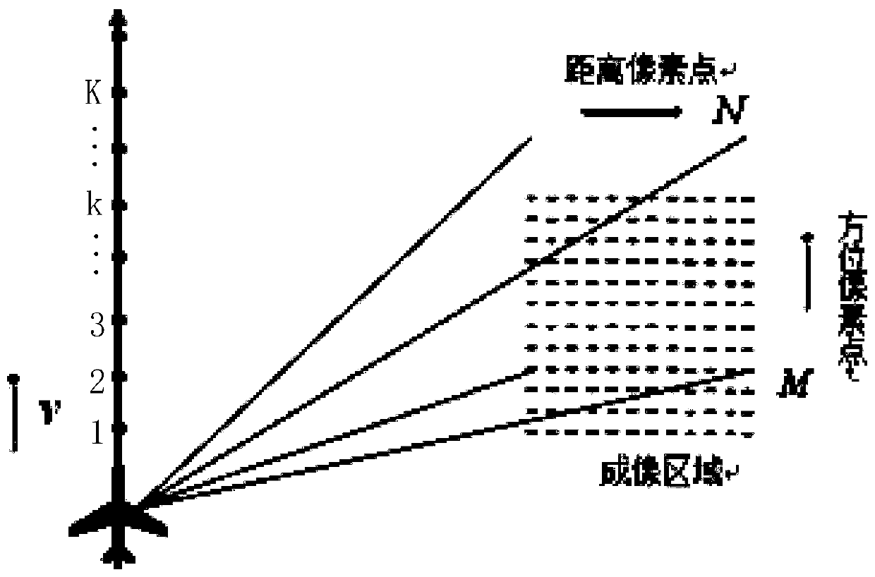
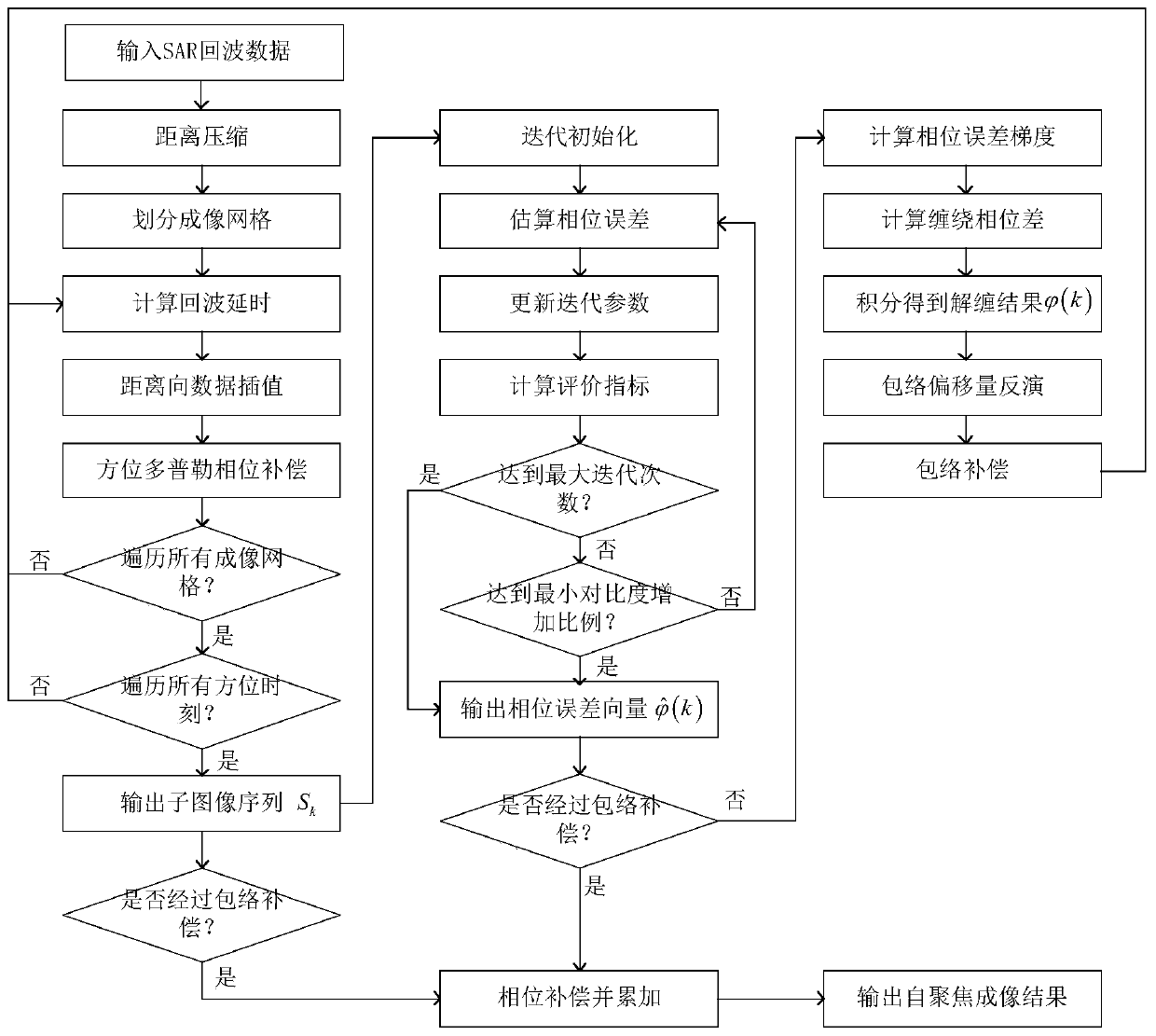

Image

  • Maneuvering trajectory synthetic aperture radar self-focusing imaging method and device and radar system
  • Maneuvering trajectory synthetic aperture radar self-focusing imaging method and device and radar system
  • Maneuvering trajectory synthetic aperture radar self-focusing imaging method and device and radar system

Examples


Embodiment Construction

[0070] In order to make the purposes, technical solutions and advantages of the application more clear, the technical solutions in the embodiments of the application will be described in more detail below in conjunction with the drawings in the embodiments of the application.

[0071] In order to perform only phase compensation on the existing motion compensation method and ignore the envelope offset, this application proposes a method to compensate the envelope offset while compensating the phase error, in order to eliminate the influence of the motion error to the greatest extent, and obtain Higher precision SAR images.

[0072] The method of this application completes the compensation of the envelope offset and phase error at the same time, estimates the error phase at each azimuth moment through the optimization method, and then unwraps the estimated phase and inverts the envelope offset at each azimuth moment. Based on this, the envelope compensation is performed, and the...


PUM


Abstract

The invention relates to a maneuvering trajectory synthetic aperture radar self-focusing imaging method. The method comprises the steps: echo data of a synthetic aperture radar are acquired; BP sub-images of the data at each azimuth moment are obtained; the phase error of each azimuth moment is estimated to obtain a phase error vector; the estimated phase error vector is unwrapped; the data envelope offset of each azimuth moment is calculated according to the unwrapped phase error vector and the emission signal wavelength of the synthetic aperture radar, and the distance vector is transferredaccording to the envelope offset to obtain echo data after envelope compensation; then the echo data subjected to distance compression is replaced with the echo data subjected to envelope compensationto obtain a sub-image at each azimuth moment; all the steps are repeated to obtain a phase error at each azimuth moment; and performing compensation on corresponding phase errors for the sub-images to obtain the full-aperture SAR image. According to the method, the envelope offset and the phase error are compensated at the same time, and the influence of the motion error on SAR imaging can be eliminated more accurately.

Description

technical field [0001] The application belongs to the technical field of radar imaging, and in particular relates to a maneuvering trajectory synthetic aperture radar self-focusing imaging method, device and radar system. Background technique [0002] Synthetic Aperture Radar (SAR) is an active active microwave remote sensing imaging radar, which obtains an equivalent large-aperture antenna through the movement of the antenna, obtains high-resolution radar azimuth, and obtains high-resolution range through pulse compression technology. rate, and finally obtain a two-dimensional high-resolution radar image of the observed scene. The motion trajectory of the antenna phase center (APC) needs to be used in SAR imaging processing. Due to factors such as measurement equipment accuracy and airflow disturbance, there is an error in the measurement value of the APC trajectory, which is called motion error, which will cause defocusing and distortion in the SAR image. Reduce image qua...

Claims


Application Information

Patent Timeline
Patent Type & Authority Applications(China)
IPC IPC(8): G01S13/90G01S7/41
CPCG01S13/90G01S7/41G01S13/9019G01S13/9017
Inventor 周灵杰张红波郭振宇
Owner LEIHUA ELECTRONICS TECH RES INST AVIATION IND OF CHINA
Learn More