
Pipe manual welding tool

A technology of welding tooling and pushing device, applied in welding equipment, auxiliary welding equipment, welding/cutting auxiliary equipment, etc., can solve the problems of robot machinery unable to weld normally, delaying product production and delivery, uneven wire feeding, etc. The welding method is simple, the material cost is saved, and the welding speed is fast.

Pending Publication Date: 2019-12-13
徐州智博机车有限公司
View PDF0 Cites 0 Cited by
  • Summary
  • Abstract
  • Description
  • Claims
  • Application Information

AI Technical Summary

Problems solved by technology

[0003] Robotic welding has been implemented for the handle pipe and inclined beams, but during the welding process, insufficient air pressure and uneven wire feeding often occur, resulting in waste of materials and damage to the welded parts. The practice of most manufacturers is to throw them away. Normal welding cannot be performed during fault maintenance, resulting in delays in product production and delivery

Method used


Image

  • Pipe manual welding tool
  • Pipe manual welding tool
  • Pipe manual welding tool

Examples


Embodiment Construction

[0024] In order to make the object, technical solution and advantages of the present invention clearer, the present invention will be further described in detail below in conjunction with the accompanying drawings and embodiments. It should be understood that the specific embodiments described here are only used to explain the present invention, not to limit the present invention.

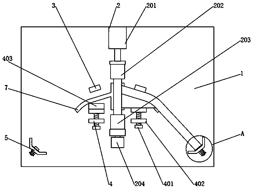
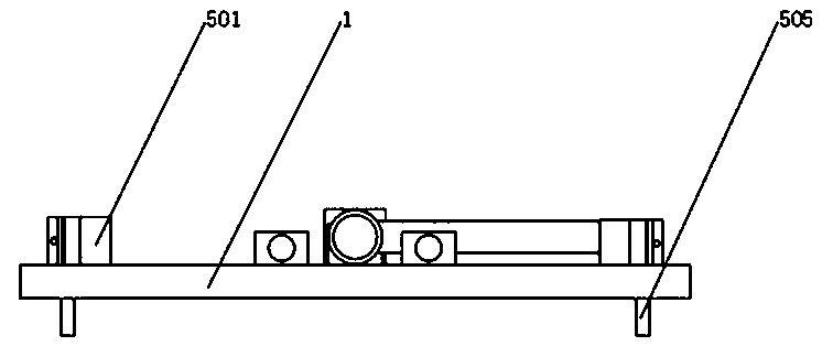
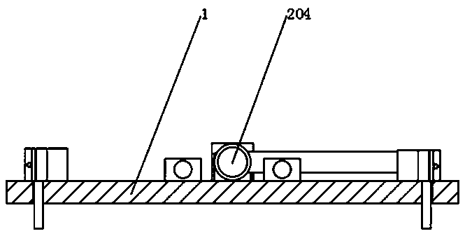
[0025] refer to Figure 1-4 , a kind of manual welding tool for pipes, including a mounting plate 1, a pushing device 2 fixed on the top of the mounting plate 1, a stopper 3, a locking device 4 and a positioning device 5 are symmetrically arranged on both sides of the pushing device 2, and the stopper 3 and the mounting plate 1 is fixedly connected, a locking device 4 is provided on one side of the block 3, and the locking device 4 is fixedly connected with the mounting plate 1, and a positioning device 5 is fixed on the top of the mounting plate 1, and the positioning device 5 is slidingly connect...


PUM


Abstract

The invention discloses a pipe manual welding tool. The pipe manual welding tool comprises a mounting plate, and a pushing device is fixed to the top of the mounting plate. Baffle plates, locking devices and positioning devices are symmetrically arranged on the two sides of the pushing device; the baffle plates are fixedly connected with the mounting plate, and the locking devices are arranged onone sides of the baffle plates; and the locking devices are fixedly connected with the mounting plate. The pipe manual welding tool is simple in structure and convenient to operate, cylinder clampingis achieved, and the repair welding efficiency of welding parts is improved, repair welding of the welding position of a robot is carried out, the material cost is saved, and the welding quality of the welding parts is improved; fast clamping and loosening are achieved through clamping cylinders, a handle drives a passive clamping block to rotate, the overturn of the entire welding parts can be realized, the welding speed is faster, and the welding method is more simple and convenient; and on the one hand, height is provided through an L-shaped baffle, so that a reinforcement plate can be conveniently placed, and on the other hand, the reinforcement plate can be conveniently fixed by tightening bolts.

Description

technical field [0001] The invention relates to the technical field of welding equipment, in particular to a manual welding equipment for handlebars. Background technique [0002] Welding, also known as welding and welding, is a manufacturing process and technology for joining metals or other thermoplastic materials such as plastics by means of heating, high temperature or high pressure. There are many energy sources for modern welding, including gas flame, electric arc, Laser, electron beam, friction and ultrasonic, etc., robotic welding has become popular. [0003] Robotic welding has been implemented for the handle pipe and inclined beams, but during the welding process, insufficient air pressure and uneven wire feeding often occur, resulting in waste of materials and damage to the welded parts. The practice of most manufacturers is to throw them away. Normal welding cannot be performed during fault repairs, resulting in delays in product production and delivery. Conte...

Claims


Application Information

Patent Timeline
Patent Type & Authority Applications(China)
IPC IPC(8): B23K37/053B23K101/06
CPCB23K37/0533B23K2101/06
Inventor 李爱华
Owner 徐州智博机车有限公司
Learn More