[0014] In order to make the objectives, technical solutions, and advantages of the embodiments of the present invention clearer, the technical solutions in the embodiments of the present invention will be described clearly and completely in conjunction with the accompanying drawings in the embodiments of the present invention. Obviously, the described embodiments It is a part of the embodiments of the present invention, not all the embodiments. Based on the embodiments of the present invention, all other embodiments obtained by those of ordinary skill in the art without creative work shall fall within the protection scope of the present invention.
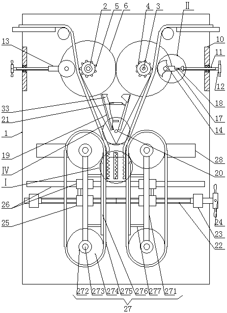
[0015] A polyurethane fiberboard bonding device for animal husbandry special wallboards, as shown in the figure, includes a support plate 1, the upper part of the front side of the support plate 1 is provided with left-right symmetrical reserved holes 2, and the reserved holes 2 are respectively installed by rotating bearings The first horizontal axis 3 and the front part of the outer periphery of the first horizontal axis 3 are respectively fixedly installed with a coaxial round roller 4, and the outer circumference of the round roller 4 are respectively fixedly installed with uniformly distributed strip pressing blocks 5, the left side strip pressing block 5 The indentation produced on the adhesive surface of the polyurethane fiberboard can be engaged with the indentation produced by the strip press block 5 on the right side of the polyurethane fiberboard. The rear part of the outer periphery of the first horizontal shaft 3 is fixed and installed. Gear 6, two first gears 6 mesh with each other, the rear end of the outer periphery of the first horizontal shaft 3 on the right side is fixedly installed with the second gear 7, the upper part of the rear side of the support plate 1 is fixedly installed with a motor 8, and the front end of the rotating shaft of the motor 8 is fixed Install the third gear 9, the third gear 9 meshes with the second gear 7, the upper edge of the front side of the support plate 1 is fixedly connected to the rear side of the left-right symmetrical ring plate 10, and the ring plate 10 is equipped with a screw rod 11 and a wire respectively. The outer ends of the rod 11 are respectively fixedly mounted with the first handwheel 12, the inner ends of the outer circumference of the screw rod 11 are respectively screwed with the internal threaded tube 13, and the internal ends of the internal threaded tube 13 are respectively fixedly connected to the outer side of the first shaft seat 14. A second horizontal shaft 15 is installed in the seat 14 respectively. The second horizontal shaft 15 is symmetrical with the corresponding first horizontal shaft 13. The outer periphery of the second horizontal shaft 15 is respectively fixedly installed with a squeeze roller 16 to support the front side of the plate 1. A symmetrical strip chute 17 is opened, and a slider 18 is movably installed in the strip chute 17. The slider 18 can only slide left and right along the strip chute 17. The front side of the slider 18 is respectively connected with the corresponding internal threaded pipe 13 The rear side of the support plate 1 is fixedly connected; the middle of the front side of the support plate 1 is fixedly connected to the rear side of the symmetrical inclined plate 19, and the front sides of the two inclined plates 19 are fixedly connected to the rear side of the same connecting plate 33. A heating lamp tube 20 perpendicular to the front side of the support plate 1 is fixedly installed at the lower end of the room, a fan 21 blowing downwards is fixedly installed at the upper part between the two inclined plates 19, and a screw 22 is provided on the lower part of the front side of the support plate 1. The screw threads at both ends of the screw 22 are in opposite directions. The two ends of the outer circumference of the screw 22 are respectively connected to the front bearing of the support plate 1 through the second shaft seat 23. The right end of the screw 22 is fixedly mounted with a second hand wheel 24. The outer circumference of the screw 22 Screw nut 25 is installed on both ends of the screw 22. The upper side of the screw 22 is provided with a linear slide slider mechanism 26. The slide rail of the linear slide slider mechanism 26 is fixedly connected to the support plate 1, and the linear slide slider mechanism 26 The two sliders are respectively fixedly connected with the corresponding nut 25, and the front side of the slider of the linear slide slider mechanism 26 is respectively fixedly installed with the vertical conveyor belt device 27. The invention has a simple structure and a clever concept. It can perform indentation treatment on the adhesive surface of the polyurethane fiberboard, and the adhesive surfaces on both sides can be meshed by dislocation indentation, which increases the contact area of the adhesive surface and makes the adhesion effect better. , Heat and melt the bonding area through the heating lamp tube, which is beneficial to the rapid heating of the bonding area. At the same time, the fan is used to blow the heating lamp tube to avoid the high temperature accumulation near the heating lamp tube causing damage to the polyurethane fiber board. At the same time, the hot air is guided to the position to be heated through the inclined plate, and the bonding surface of the position to be heated is preheated to reduce the heat loss of the heating lamp. The conveyor belt device is used to form a clamping force on the bonded polyurethane fiberboard, which can extend the clamp Tight time can further increase the bonding effect, and at the same time, use the conveyor belt device to form a downward pulling force on the polyurethane fiberboard after bonding, so that the polyurethane fiberboard can move downward, which can meet actual needs and is suitable for promotion. When using the present invention, firstly pass the ends of the two polyurethane fiberboards to be bonded between the round roller 4 and the squeeze roller 16, and both ends of the two polyurethane fiberboards are located between the two conveyor belt devices 27. Then screw the screw 11 through the first hand wheel 12, so that the internally threaded tube 13 drives the second horizontal shaft 15 and the squeeze roller 16 to move inward through the first shaft seat 14, until the squeeze roller 16 forms the outer side of the polyurethane fiberboard With sufficient inward pressing force, under the action of the pressing force, the strip pressing block 5 can form an indentation on the inner side of the polyurethane fiberboard, and then the screw 22 is screwed through the second hand wheel 24, so that the nut 25 passes through a straight line The sliding block of the sliding rail mechanism 26 drives the conveyor belt devices 27 on both sides to move toward each other to form a clamping force at one end of the two polyurethane fiberboards between the inner pair of the conveyor belt device 27, and the conveyor belt device 27 and the squeeze roller 16 The two polyurethane fiberboards are in the drawn state. At this time, the heating lamp 20 and the fan 21 are sequentially energized, and the heating lamp 20 bakes and heats the polyurethane fiberboard bonding joints, so that the polyurethane fiberboard bonding surface can quickly reach the bonding temperature At the same time, the fan 21 blows downwards to prevent the heat generated by the heating lamp tube 20 from losing upwards, and at the same time to avoid the high temperature accumulation near the heating lamp tube 20, which may cause excessive temperature to adversely affect the polyurethane fiberboard, and make the hot air upward along the outside of the inclined plate 19 The flow preheats the adhesive surface near the swash plate 19; then energizes the motor 8, the shaft of the motor 28 drives the second gear 7 to rotate through the third gear 9, and the second gear 7 drives the first horizontal shaft 3 on the right to rotate , The first horizontal shaft 3 on the right side drives the first horizontal shaft 3 on the left to rotate through the first gear 6, the first horizontal shaft 3 drives the round roller 4 to rotate, and the round roller 4 drives the bar press block 5 to rotate. Block 5 forms an indentation on the adhesive surface of the polyurethane fiberboard. The indentation produced by the strip press block 5 on the left on the adhesive surface of the polyurethane fiberboard can be generated with the strip press block 5 on the right on the adhesive surface of the polyurethane fiberboard. The indentation is dislocated and meshing, and at the same time, the polyurethane fiberboard is formed as a tensile force. The adhesive surface of the polyurethane fiberboard moves downward. At the same time, the first horizontal shaft 3 drives the conveyor 27 through the transmission device to operate, and the conveyor 27 maintains the adhesion to the polyurethane fiberboard. The latter pressing force simultaneously forms a downward pulling force on the polyurethane fiberboard. The speed at which the polyurethane fiberboard passes through the round roller 4 is equal to the speed at which the polyurethane fiberboard is pulled down by the conveyor belt device 27, so that the two between the conveyor belt device 27 and the squeeze roller 16 The polyurethane fiberboard is in a drawn state.
[0016] Specifically, as shown in the figure, the conveyor belt device 27 in this embodiment includes a vertical rod 271. The middle of the rear side of the vertical rod 271 is respectively fixedly connected to the front side of the slider of the corresponding linear slide rail slider mechanism 26. The two ends of the rod 271 are respectively fixedly installed with a third shaft seat 272, the third shaft seat 272 is equipped with a third horizontal shaft 273 respectively, and the front part of the third horizontal shaft 273 is fixedly installed with a timing belt wheel 274, the upper and lower two synchronous The outer circumference of the pulley 274 is fitted with the same timing belt 275. The upper and lower timing pulleys 274 are driven by the timing belt 275. The inner side of the timing belt 275 is provided with a vertical support plate 276. The vertical support plates 276 are respectively connected to the corresponding The vertical rod 271 is fixedly connected by a connecting rod 277, and the inner side of the vertical support plate 276 is in sliding contact with the inner side of the corresponding timing belt 275. Rotate the lead screw 22 to make the nut 25 drive the conveyor belt device 27 to move toward each other through the slider of the linear slide slider mechanism 26, so that the inner periphery of the timing belt 275 forms a pressing force on the polyurethane fiberboard between the two conveyor belt devices 27. Apply a clockwise rotation force to the third horizontal axis 273 on the upper left side, apply a counterclockwise rotation force to the third horizontal axis 273 on the upper right side, and rotate the third horizontal axis 273 on the upper left side and the third horizontal axis 273 on the upper right side. At the same speed, the conveyor belt devices 27 on both sides maintain the same clamping force of the polyurethane fiberboard between them and pull the polyurethane fiberboard to move downward. The vertical support plate 276 provides inward force for the corresponding timing belt 275 This prevents the timing belt 275 from changing its clamping force on the polyurethane fiberboard due to its elastic deformation.
[0017] Specifically, as shown in the figure, the central part of the front side of the support plate 1 described in this embodiment is provided with a transverse strip through slot 28, and the rear end of the third horizontal shaft 273 on the upper side passes through the strip through slot 28. On the rear side of the support plate 1, the rear end of the third horizontal shaft 273 on the upper side and the rear end of the first horizontal shaft 3 adjacent to the upper side are respectively provided with a transmission device 29, and the first horizontal shaft 3 on the left Turning counterclockwise through the corresponding transmission device 29 drives the third horizontal axis 273 on the upper left side to rotate clockwise, and turning the first horizontal axis 3 on the right side clockwise through the corresponding transmission device 29 drives the third horizontal axis 273 on the upper right side counterclockwise Rotate. The rear end of the upper third horizontal shaft 273 and the rear end of the first horizontal shaft 3 adjacent to the upper side are respectively driven by the transmission device 29, which can make the indentation speed of the strip pressing block 5 on the polyurethane fiberboard and the conveyor belt device 27 The speed of pulling down the polyurethane fiberboard is proportional, that is, the faster the strip pressing block 5 makes the polyurethane fiberboard indentation, the faster the conveyor belt device 27 pulls the polyurethane fiberboard downward, which facilitates the coordination between the two speeds.
[0018] Further, as shown in the figure, the transmission device 29 in this embodiment includes a first helical gear 291, and the rear end of the first horizontal shaft 3 and the rear end of the upper third horizontal shaft 273 are respectively fixedly installed with coaxial The middle of the first helical gear 291 and the rear side of the first helical gear 291 are respectively connected with the front end of the inverted L rod 292, the inner end of the inverted L rod 292 is respectively connected with the middle of the outer side of the second helical gear 293, and the second helical gear 293 is respectively It meshes and cooperates with the corresponding first helical gear 291. The inner middle of the lower second helical gear 293 is respectively fixedly connected to the lower end of the square tube 294. The square rod 295 is movably installed in the square tube 294. The square rod 295 can only be installed in the corresponding The square tube 294 moves up and down, and the upper ends of the square rods 295 are respectively fixedly connected to the middle inside the corresponding upper second helical gear 293. The first horizontal shaft 3 drives the upper second helical gear 293 to rotate through the upper first helical gear 291, the upper second helical gear 293 drives the square rod 295 to rotate, the square rod 295 drives the square tube 294 to rotate, and the square tube 294 drives the second helical gear 293 on the lower side to rotate. The second helical gear 293 on the lower side drives the corresponding third horizontal shaft 273 to rotate through the first helical gear 291 on the lower side. When the conveyor 27 moves left and right, the upper The third horizontal shaft 273 drives the corresponding lower first helical gear 291 to move left or right, and the square rod 295 moves up or down along the corresponding square tube 294.
[0019] Furthermore, as shown in the figure, the top of the front side of the support plate 1 in this embodiment is fixedly connected to the rear side of the symmetrical lateral support plate 30. The inner side of the lateral support plate 30 is provided with a rotating roller 31. The rear ends of the support plate 1 are respectively connected with the front side bearings. The polyurethane fiberboard to be bonded is placed on the top side of the lateral support plate 30, and the lower end of the polyurethane fiberboard to be bonded passes around the inner side of the rotating roller 31. When the polyurethane fiberboard moves downward, the corresponding rotating roller 31 is driven to rotate.
[0020] Furthermore, as shown in the figure, a baffle 32 fixedly connected to the support plate 1 is provided above the heating lamp tube 20 in this embodiment. The baffle 32 can prevent the heating lamp tube 20 from directly baking the fan 21, and at the same time, reduce the heat generated by the heating lamp tube 20 from directly losing upward.
[0021] Finally, it should be noted that the above embodiments are only used to illustrate the technical solutions of the present invention, not to limit it; although the present invention has been described in detail with reference to the foregoing embodiments, those of ordinary skill in the art should understand that: The technical solutions recorded in the foregoing embodiments are modified, or some of the technical features are equivalently replaced; these modifications or replacements do not cause the essence of the corresponding technical solutions to deviate from the spirit and scope of the technical solutions of the embodiments of the present invention.