
A capacitor production inkjet equipment

A technology for capacitors and inkjet coding, which is applied in capacitors, capacitor manufacturing, circuits, etc. It can solve problems such as polluting the working environment, affecting ink output, and time-consuming and laborious cleaning of nozzles, and achieves the effects of improving dissolution efficiency and preventing liquid accumulation

Inactive Publication Date: 2020-08-21
陈灯芳
View PDF8 Cites 0 Cited by
  • Summary
  • Abstract
  • Description
  • Claims
  • Application Information

AI Technical Summary

Problems solved by technology

[0003] In view of the above problems, the present invention solves the problem that the ink left inside the nozzle is not easy to clean after use. If you simply wipe the surface of the nozzle, or disassemble the nozzle and use cleaning equipment to clean it completely, the former will easily cause the remaining ink to dry up if it has not been used for a long time. Blocking the nozzles affects the ink output; the latter is time-consuming and laborious to clean the nozzles, and the disassembled nozzles are easy to drop on the workbench due to the residual ink at the nozzles, polluting the working environment. A kind of capacitor production inkjet equipment

Method used


Image

  • A capacitor production inkjet equipment
  • A capacitor production inkjet equipment
  • A capacitor production inkjet equipment

Examples


Embodiment

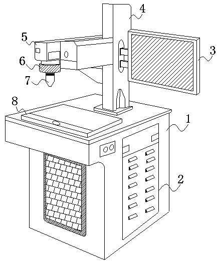
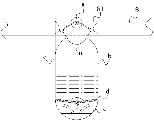
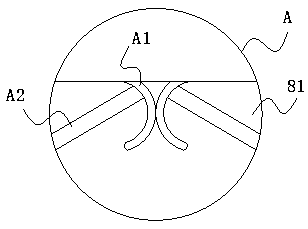
[0027] Such as Figure 1-Figure 5 As shown, the present invention provides a kind of inkjet equipment for producing capacitors. Its structure includes a main box 1, a heat dissipation cover 2, a computer board 3, a lifting column 4, a machine head 5, a distance adjustment plate 6, a nozzle 7, and a workbench 8. The circuit system inside the lifting column 4, the computer board 3, the machine head 5, and the distance adjusting disc 6 are all located in the main box 1, and the heat dissipation cover 2 is installed on the main box 1, and the main box 1 is opposite to the nozzle 7. A workbench 8 is fixed on the position, the computer board 3 is controlled by the machine head 5 and the nozzle 7, the lifting column 4 is movable to cooperate with the machine head 5, and a nozzle is arranged at the bottom of the end of the machine head 5 away from the lifting column 4 7. The nozzle 7 cooperates with the distance adjustment disc 6, and the position where the workbench 8 is facing the n...


PUM


Abstract

The invention discloses capacitor production code spraying equipment. The capacitor production code spraying equipment structurally comprises a main machine case, a heat dissipation cover, a computerboard, a lifting column, a machine head, a distance adjusting disc, a nozzle and a workbench. Circuit systems in the lifting column, the computer board, the machine head and the distance adjusting disc are arranged in the main machine case. The main machine case is provided with the heat dissipation cover. The workbench is fixed to the position, opposite to the nozzle, of the main machine case. The computer board controls the machine head and the nozzle. The workbench is provided with a circular notch, a hollow inner container integrated with the circular notch is filled with liquid which is purified water, and under the action of a heating base, the purified water becomes warm water. Every time when the nozzle finishes work, the lifting column pushes the nozzle to descend and penetrate through the circular notch perpendicularly opposite to the nozzle, the warm water in the hollow inner container is utilized for dissolving ink dried and solidified on the nozzle, and since the liquid has mobility, the warm water can enter the interior along a nozzle port, the dry ink is sufficiently dissolved, and meanwhile the dissolving efficiency is improved.

Description

technical field [0001] The invention relates to the field of capacitor production equipment, in particular, it is a coding equipment for capacitor production. Background technique [0002] There are many types of inkjet printers, and inkjet printers can be divided into large-character inkjet printers, small-character inkjet printers, and high-resolution inkjet printers according to the size of the inkjet inkjet printers, and can be classified into ink inkjet printers and laser inkjet printers according to the consumables used , as an inkjet printer, when the capacitor is used to do small character coding, the nozzle diameter is small, and the ink left inside the nozzle is not easy to clean up after use. If you simply wipe the surface of the nozzle, or disassemble the nozzle and use cleaning equipment for comprehensive cleaning, The former is likely to cause the remaining ink to dry up and block the nozzle if it is not used for a long time, affecting the ink output; the latte...

Claims


Application Information

Patent Timeline
Patent Type & Authority Patents(China)
IPC IPC(8): B41J3/407B41J2/135B41J2/14B41J2/165H01G13/00
CPCB41J2/135B41J2/14B41J2/165B41J3/4073H01G13/00
Inventor 陈宏伟
Owner 陈灯芳
Learn More