Hydraulic workover rig

A workover rig and hydraulic technology, which is applied to drilling equipment, wellbore/well components, production fluids, etc. It can solve the problems of complex structure, increased work difficulty and danger, and no automatic pumping function, etc., and achieves simple operation Effect

Pending Publication Date: 2019-12-13
青岛北海俊惠电子仪表有限公司
View PDF0 Cites 0 Cited by
  • Summary
  • Abstract
  • Description
  • Claims
  • Application Information

AI Technical Summary

Problems solved by technology

This kind of work and transmission mode has complex structure, cumbersome control, poor safety, and it is very prone to collision accidents, low work efficiency and power utilization efficiency, high consumption of fuel and wire rope, complicated work preparation procedures, high moving and maintenance costs, The problem of dripping and leaking is serious, and it does not have the function of automatic pumping
[0003] Although a small number of workover rigs have used a single hydraulic cylinder to lift and lower the operation, the technology is still immature, and the irregular rotation of the single hydraulic cylinder causes the hook to shake, which increases the difficulty of the work and dangerous
Moreover, the workover rig with a single hydraulic cylinder has insufficient lifting power and low speed, and does not have the function of automatic swabbing, which cannot meet the increasing requirements of oilfield operations

Method used


Image

  • Hydraulic workover rig
  • Hydraulic workover rig
  • Hydraulic workover rig

Examples


Embodiment Construction

[0038] The present invention will be described in detail below in conjunction with the embodiments and the accompanying drawings. It should be noted that the described embodiments are only intended to facilitate the understanding of the present invention, rather than limiting it in any way.

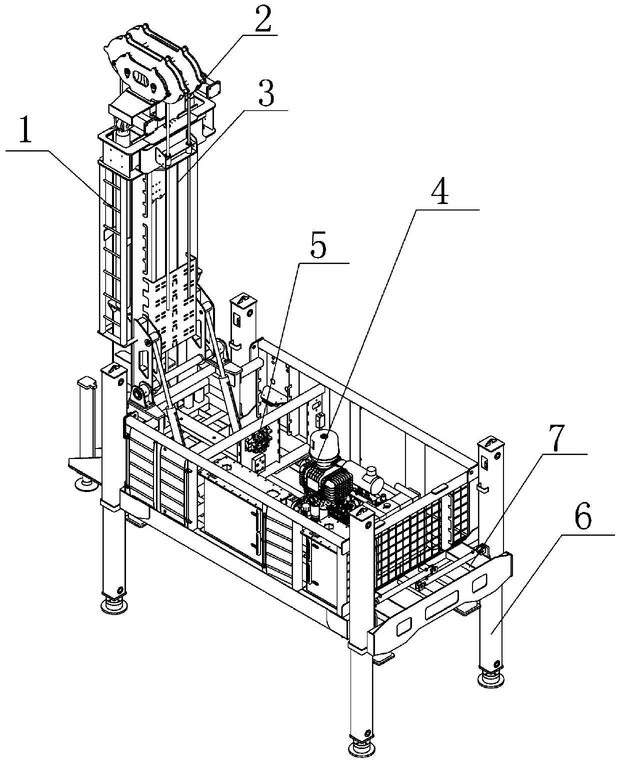
[0039] Such as Figure 1-6 As shown, a hydraulic workover rig provided by the present invention includes a workover lifting module 1, a swabbing module 2, and a hydraulic winch module 3, which are used to provide the workover lifting module 1, the swabbing module 2 and the hydraulic winch module 3 The power module 4 of power is used to control the workover lifting module 1, the pumping module 2, the hydraulic winch module 3 and the control module 5 of the power module 4, and is used to support the workover lifting module 1, the pumping module 2, the hydraulic The outrigger module 6 and the unit structure module 7 of the winch module 3 , the power module 4 and the control module 5 .

[00...


PUM


Abstract

The invention relates to a hydraulic workover rig. The hydraulic workover rig comprises a workover lifting module, a swabbing module, a hydraulic winch module, a power module used for providing powerfor the workover lifting module, the swabbing module and the hydraulic winch module, a control module used for controlling actions of the workover lifting module, the swabbing module, the hydraulic winch module and the power module, a supporting leg module for supporting the above modules, and a unit structure module. The hydraulic workover rig has the beneficial effects that two working modes ofworkover and swabbing operation are achieved through the up-down lifting movement of a hydraulic oil cylinder, a roller, a derrick and a roller brake system of a traditional workover rig are replaced,and the mode of electric and liquid transmission and control is adopted to meet the increasingly stringent environmental protection requirements; and moreover, the workover rig also has the advantages that the risk of crashing into a crown block is avoided, the transmission efficiency is high, the transportation is convenient, the structure is simplified, the part replacement cost and the maintenance cost are low, the operation preparation time is short, the lifting speed is high, the mechanical transmission part is few, and the problem of dripping leakage is basically eliminated.

Description

technical field [0001] The invention relates to underground oil and gas extraction equipment, in particular to a hydraulic workover machine. Background technique [0002] Workover and swabbing are the main processes of downhole operations in oil fields, and workover rigs are currently the main operating equipment for well workover and swabbing. The traditional workover rig mainly adopts the working form of drum-derrick-crown-traveling block. First, the power of the engine or motor is transmitted to the drum through the transmission, transfer case, transmission shaft, angle transmission box, etc., and the drum must cooperate with the derrick. , crown block, traveling block, etc. can realize the lifting and lowering action in the workover, and does not have the automatic swabbing function. This kind of work and transmission mode has complex structure, cumbersome control, poor safety, and it is very prone to collision accidents. The problem of dripping and leaking is serious,...

Claims


Application Information

Patent Timeline
Patent Type & Authority Applications(China)
IPC IPC(8): E21B19/086E21B43/00E21B19/084
CPCE21B19/084E21B19/086E21B43/126
Inventor 曲扬高俊
Owner 青岛北海俊惠电子仪表有限公司
Why Eureka
Try Eureka