Polarization-adjustable laser beam expansion collimator

A laser beam expander and collimator technology, which is applied in the direction of lasers, laser components, laser optical equipment, etc., can solve the problem that the polarization of laser beams cannot be adjusted and maintained accurately, and achieve smaller occupied space, reduced length, and reduced undulating effect

Pending Publication Date: 2019-12-13
XI'AN INST OF OPTICS & FINE MECHANICS - CHINESE ACAD OF SCI
View PDF0 Cites 7 Cited by
  • Summary
  • Abstract
  • Description
  • Claims
  • Application Information

AI Technical Summary

Problems solved by technology

[0006] In order to overcome the defect that the existing beam expander collimator cannot accurately adjust and maintain the polarization of the input laser beam, the present invention provides a polarization-adjustable laser beam for magneto-optical traps, optical traps, and other cold atomic physics experimental systems. Laser beam expander collimator, the invention can precisely adjust the collimation characteristics and polarization characteristics of the laser beam to meet the needs of high-quality cold atomic group preparation, and also has the characteristics of small size and good reliability

Method used


Image

  • Polarization-adjustable laser beam expansion collimator
  • Polarization-adjustable laser beam expansion collimator
  • Polarization-adjustable laser beam expansion collimator

Examples


Embodiment 1

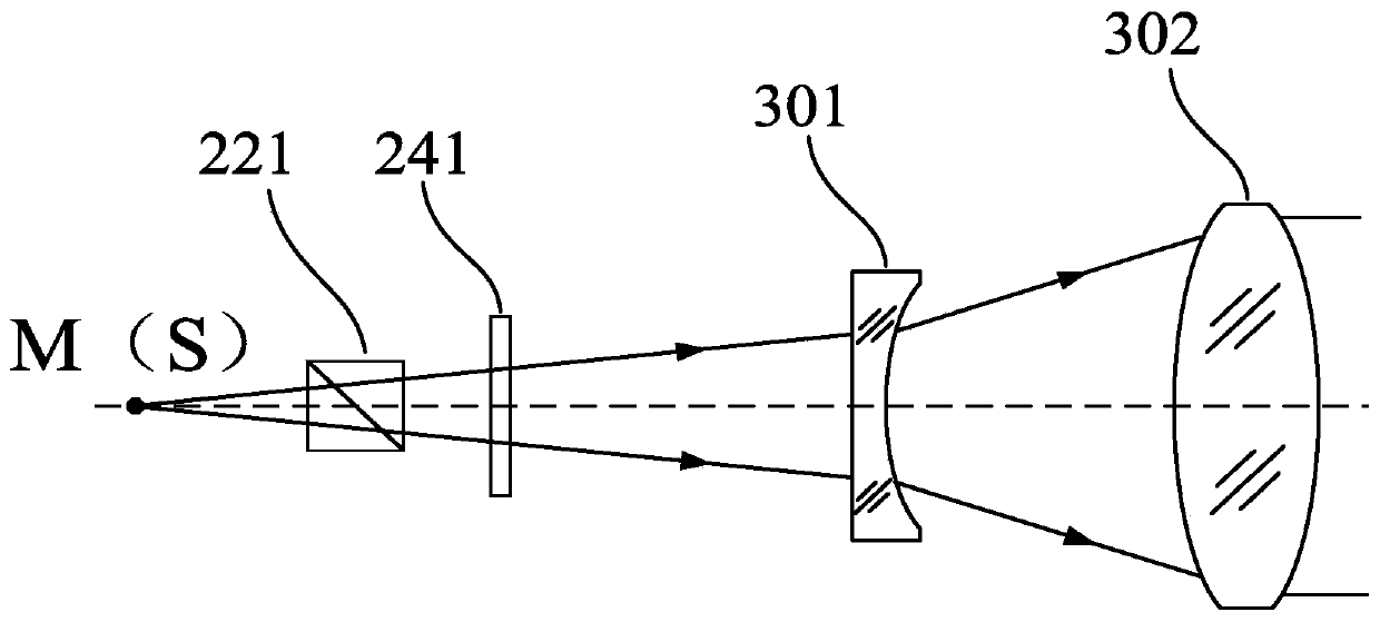
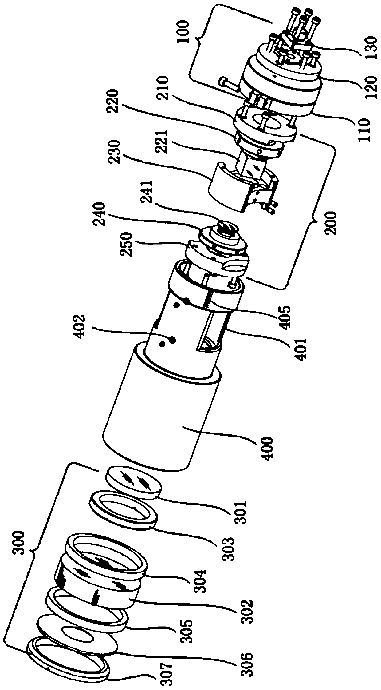
[0046] Such as figure 2 As shown, the polarization-adjustable laser beam expander and collimator of this embodiment includes a lens barrel 400, and a laser input collimation system 100, a polarization adjustment system 200, and a beam expander system 300 arranged in sequence along the laser transmission direction.

[0047] The lens barrel 400 is used to place the polarization adjustment system 200 and the beam expander system 300; the laser input collimation system 100 is used to introduce the laser beam and collimate the laser beam; the polarization adjustment system 200 is used to align the polarization of the collimated laser beam The state is precisely adjusted and maintained; the beam expander system is used to expand the laser beam after adjusting the polarization state.

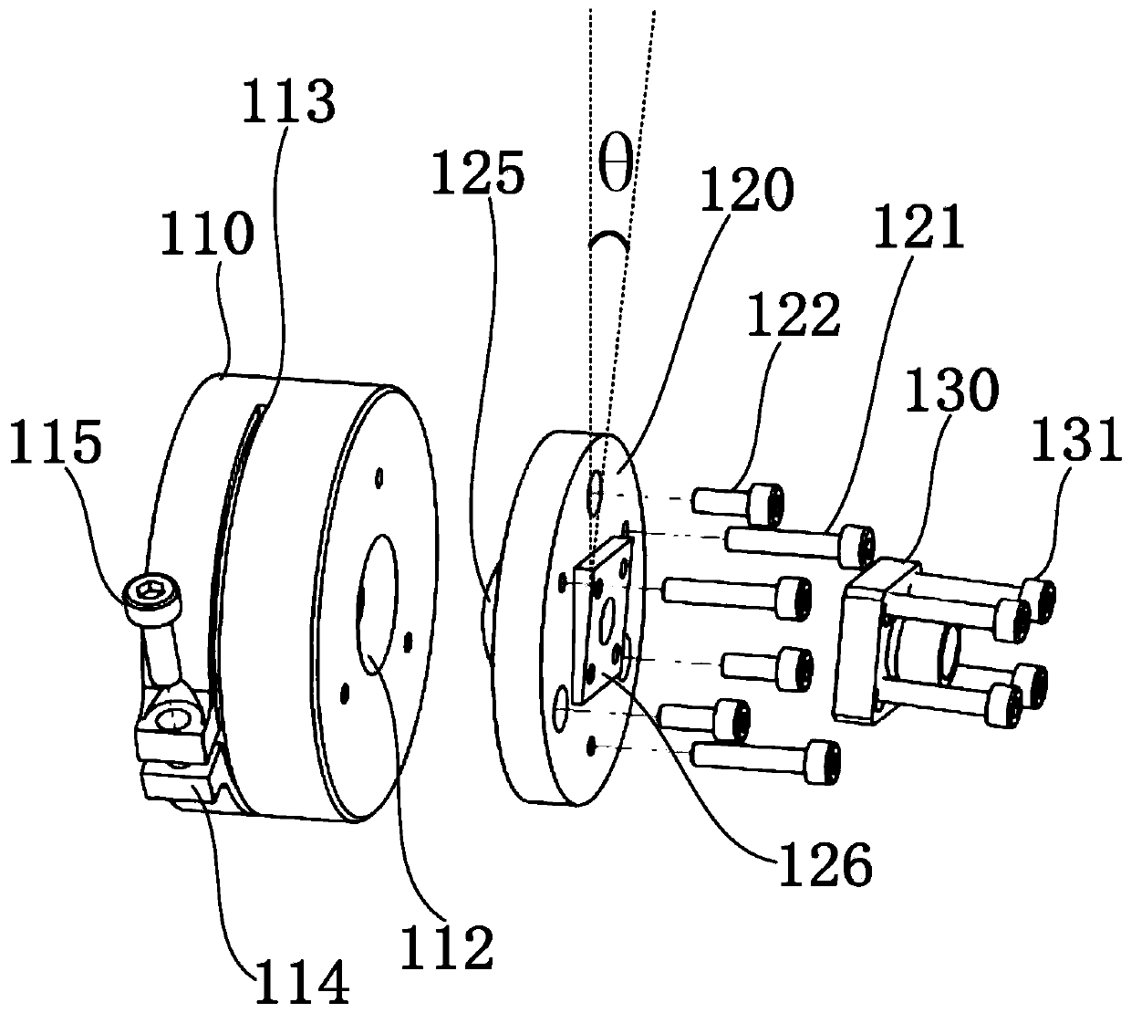
[0048] Such as image 3 As shown, the laser input collimation system 100 includes a fiber coupling head 130, a direction adjustment plate 120 and a direction adjustment base 110 arranged in sequence ...

Embodiment 2

[0074] see Figure 7 , Figure 8 , compared with Embodiment 1, the structures, functions and adjustment methods of the laser input collimation system 100, polarization adjustment system 200, and beam expander system 300 in this embodiment are exactly the same as those in Embodiment 1, and the only difference lies in Embodiment 2 A 45-degree rectangular plane mirror 310 and its mechanical fixing and adjustment structure are added to the optical path, and the lens barrel 400 becomes an "L" shape according to the characteristics of the optical path.

[0075] The 45-degree rectangular plane mirror 310 is fixedly connected to the support plate 421 by glue or screws, and the support plate 421 is fixedly connected to the rear cover plate 422 by three third screws 423, and the three third screws 423 are distributed at 120 degrees on the plane , the rear cover 422 is fixedly connected to the outer frame 425 through four fourth screws 424 , and the outer frame 425 is fixedly connected ...


PUM


Abstract

In order to overcome the defect that the polarization of an input laser beam cannot be accurately adjusted and maintained by an existing beam expansion collimator, the invention provides a polarization-adjustable laser beam expansion collimator employing magnetic optical trap, optical trap and other structure cold atomic physical experiment systems. A polarization prism and a slide of which polarization axis can be independently and accurately adjusted are arranged in an optical path, the polarization state of a light beam input from a polarization-maintenance optical fiber can be accurately adjusted and maintained, the fluctuation of a laser power is reduced, the change of the polarization state of an emergent light beam caused by the polarization-maintenance optical fiber is eliminated,and the requirement of high-quality ultracold atom preparation is met.

Description

technical field [0001] The invention relates to a polarization-adjustable laser beam expander collimator capable of converting laser light transmitted by an optical fiber into a large-diameter parallel laser beam. The laser beam generated by the laser beam expander collimator is used to generate a Stable and ultra-low temperature cold atomic groups can be used in cold atomic physics experimental systems. Background technique [0002] In cold atom physics experiments and instruments and equipment using cold atoms as the working medium, obtaining ultra-low temperature atomic groups with a stable number of atoms is the primary technical problem to be solved. At present, the most effective way to obtain ultracold atoms is to use laser beams to interact with atoms to prepare ultracold atoms. According to the theory of laser cooling, the common methods of laser cooling atoms are mainly optical traps and magneto-optical traps. Both methods produce ultracold atoms through polarizat...

Claims


Application Information

Patent Timeline
Patent Type & Authority Applications(China)
IPC IPC(8): G02B27/28G02B27/30G02B27/09H01S3/00
CPCG02B27/0955G02B27/286G02B27/30H01S3/005
Inventor 贾森王先华蔡勇解来运
Owner XI'AN INST OF OPTICS & FINE MECHANICS - CHINESE ACAD OF SCI
Why Eureka
Try Eureka