Composite multi-level power conversion circuit and method
A conversion circuit and multi-level technology, applied in the direction of converting AC power input to DC power output, output power conversion devices, electrical components, etc., can solve problems such as complex topology and difficult balance of capacitor voltage, and achieve simplified topology , Modulation strategy is simple, the effect of more output levels
- Summary
- Abstract
- Description
- Claims
- Application Information
AI Technical Summary
Problems solved by technology
Method used
Image
Examples
Embodiment 1
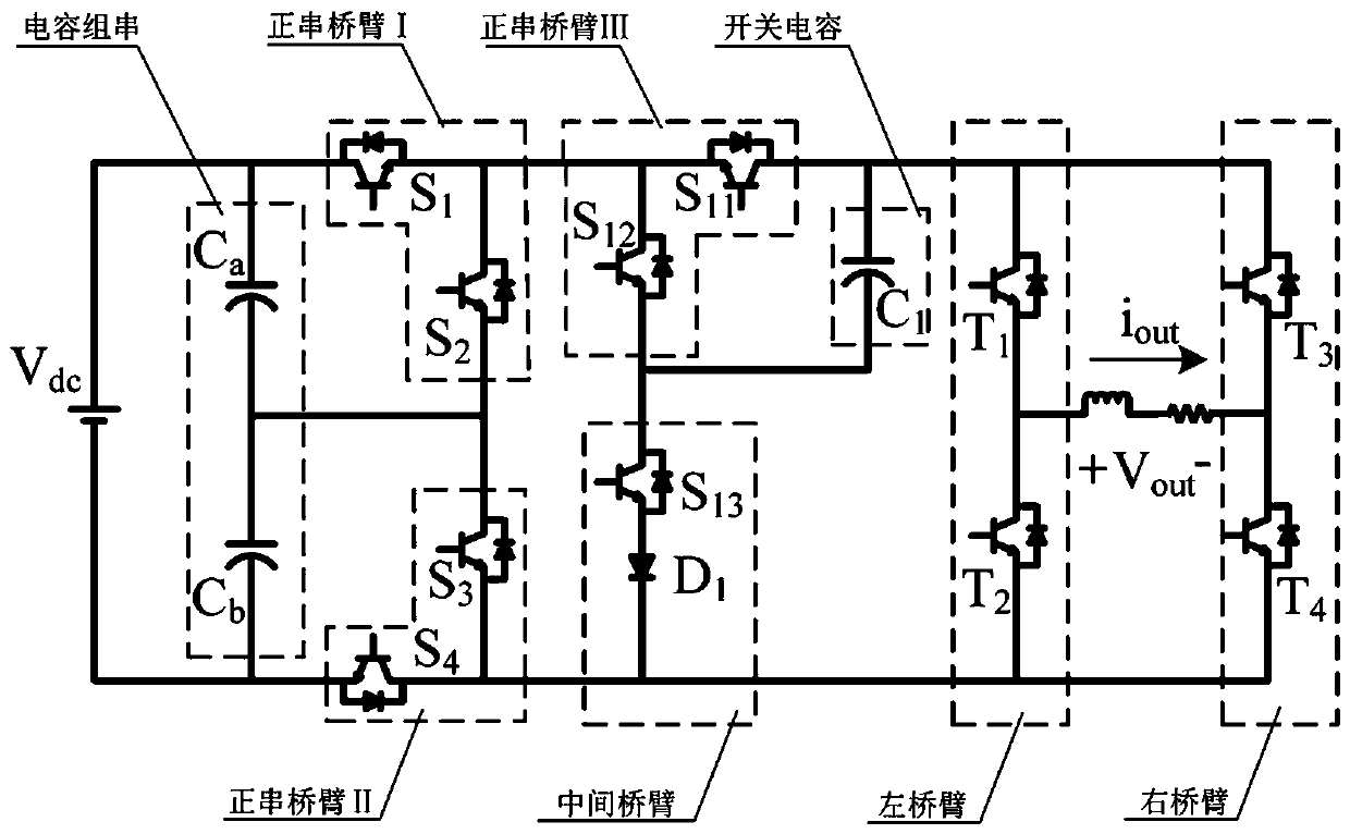
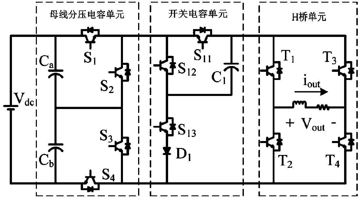
[0028] as attached figure 1 And attached figure 2 As shown, a composite multi-level power conversion circuit includes a single DC bus power supply, a bus voltage dividing capacitor unit, an H bridge unit and at least one switched capacitor unit; the bus voltage dividing capacitor unit includes a capacitor string, a positive string Bridge arm I and positive series bridge arm II; the capacitor string is connected in parallel with the DC bus power supply; one end of the positive series bridge arm I is respectively connected to the anode of the DC bus power supply and one end of the capacitor string, The other end of the positive series bridge arm I is respectively connected to the midpoint of the capacitor string and one end of the positive series bridge arm II, and the other end of the positive series bridge arm II is connected to the other end of the capacitor string respectively. One end and the cathode of the DC bus power supply; each of the switched capacitor units include...
Embodiment 2
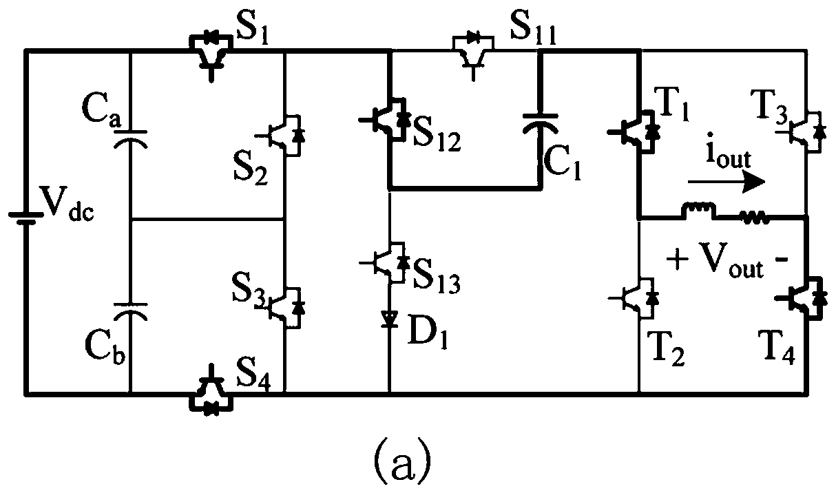
[0032] This embodiment provides a specific implementation of a bus voltage dividing capacitor unit, the bus voltage dividing capacitor unit includes an electrolytic capacitor C a , electrolytic capacitor C b , switch tube S 1 , switch tube S 2 , switch tube S 3 and switch tube S 4 ; The electrolytic capacitor C a and the electrolytic capacitor C b Constitute the capacitor string, the switch tube S 1 and the switching tube S 2 Constitute the positive series bridge arm I, the switching tube S 3 and the switching tube S 4 Constitute the positive series bridge arm II; wherein, the electrolytic capacitor C a The anode of the switching tube S 1 input and the DC bus supply V dc connected to the anode of the switching tube S 1 The output terminal of the switching tube S 2 The input terminal is connected; the switch tube S 2 The output terminals are respectively connected with the switching tube S 3 The input terminal, the electrolytic capacitor C a the cathode and the ...
Embodiment 3
[0058] This embodiment provides a specific implementation manner of the expanded composite multilevel power conversion circuit. as attached Figure 16 As shown, the present invention can further improve the quantity and boost gain of the output level of the composite multilevel power conversion circuit by setting a plurality of switched capacitor units connected in parallel by expanding the switched capacitor unit; when the switched capacitor unit When the number of is greater than 1, multiple switched capacitor units are connected in parallel.
[0059] That is to say, when the number of switched capacitor units N=1, the composite multi-level power conversion circuit outputs nine different levels at most; when the number of switched capacitor units N≥2, the composite multi-level power conversion circuit The level power conversion circuit has 4N+5 working modes, that is, every time a switched capacitor unit is added, the number of output levels of the composite multi-level pow...
PUM
 Abstract
Description
Claims
Application Information
 - R&D
- Intellectual Property
- Life Sciences
- Materials
- Tech Scout
- Unparalleled Data Quality
- Higher Quality Content
- 60% Fewer Hallucinations
Browse by: Latest US Patents, China's latest patents, Technical Efficacy Thesaurus, Application Domain, Technology Topic, Popular Technical Reports.
© 2025 PatSnap. All rights reserved.Legal|Privacy policy|Modern Slavery Act Transparency Statement|Sitemap|About US| Contact US: help@patsnap.com


