Cervical vertebra rehabilitation treatment device
A technology for rehabilitation therapy and cervical spine, applied in the field of medical devices, can solve the problems of ligament collateral damage, poor effect, and single function of the cervical spine, and achieve the effect of preventing outward loss, better treatment effect, and promoting circulation.
- Summary
- Abstract
- Description
- Claims
- Application Information
AI Technical Summary
Problems solved by technology
Method used
Image
Examples
Embodiment 1
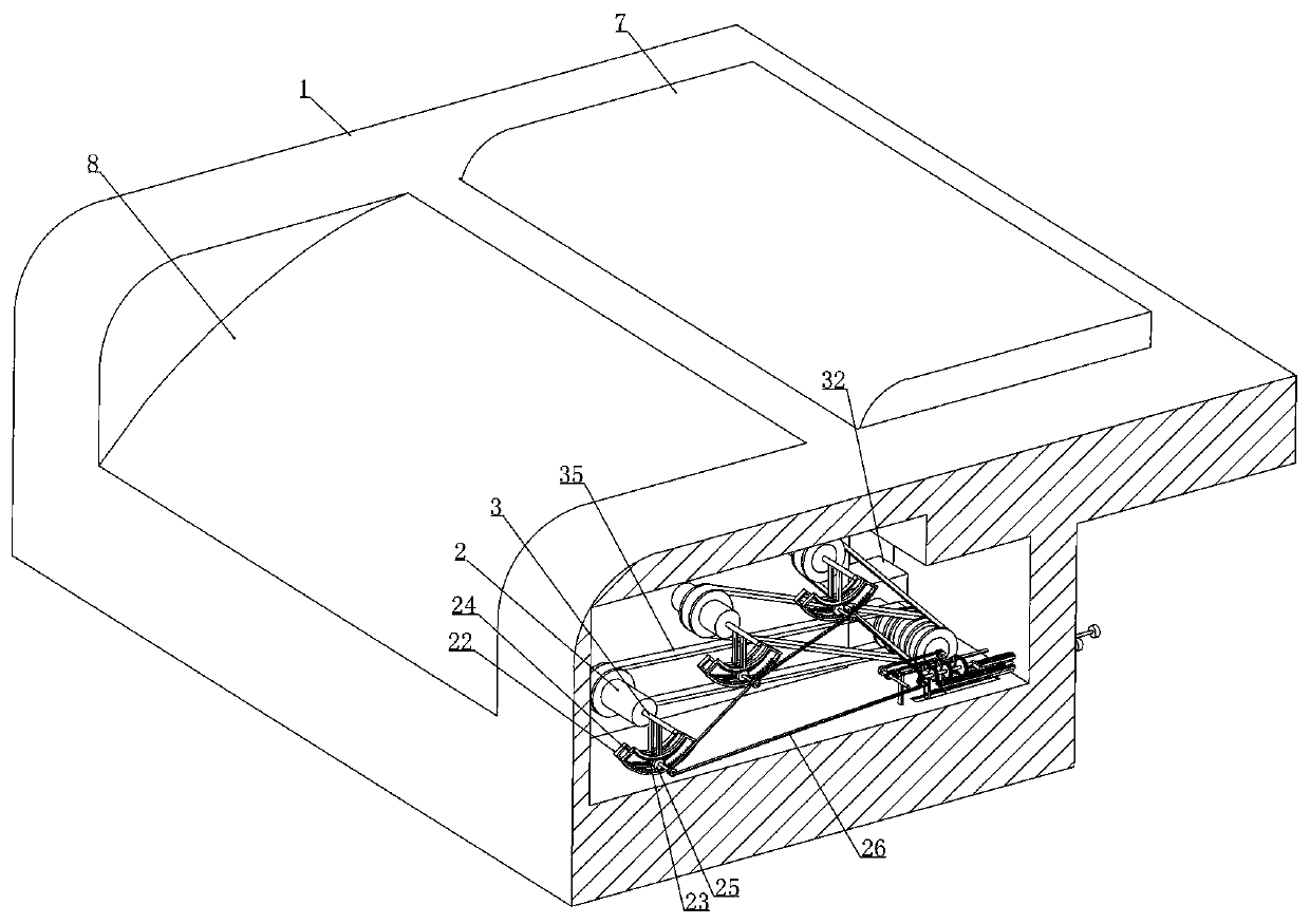
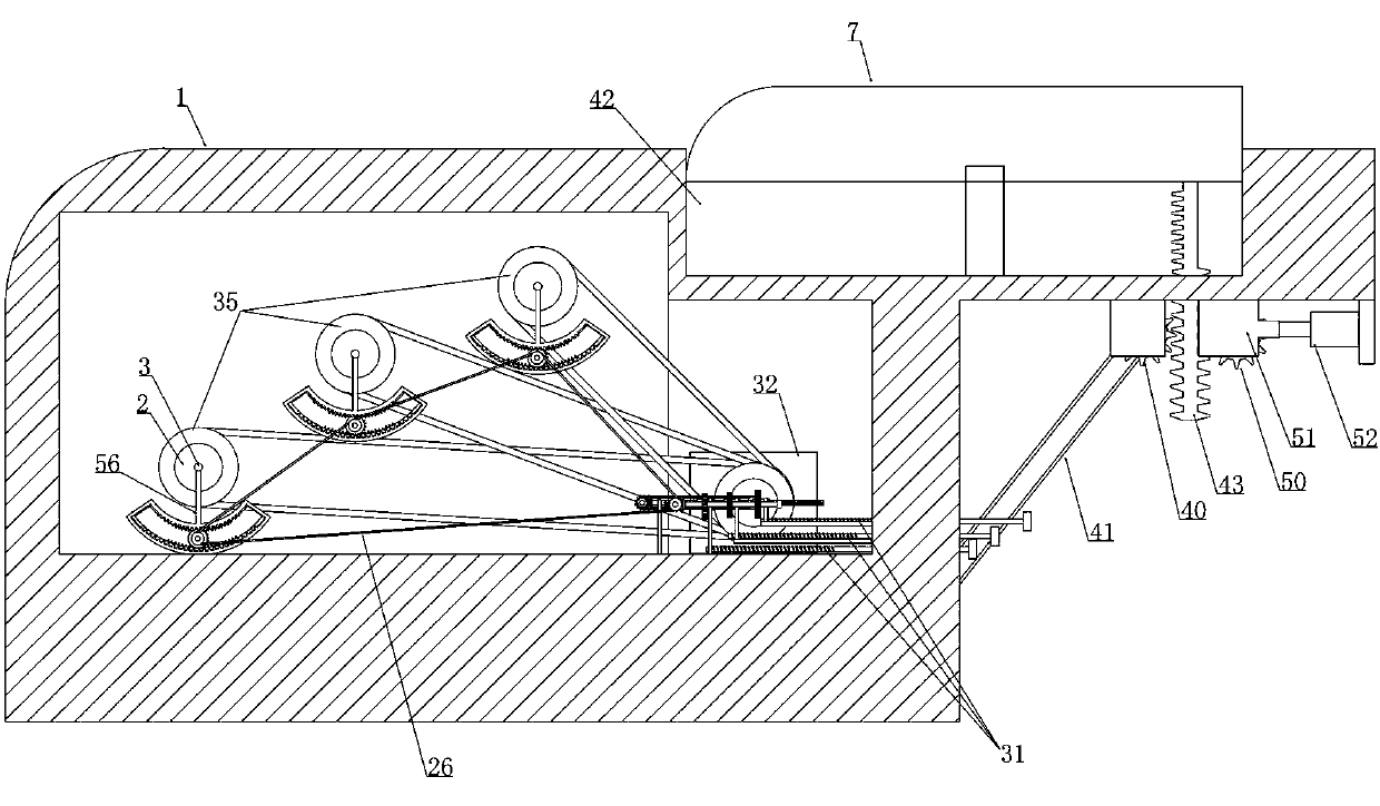
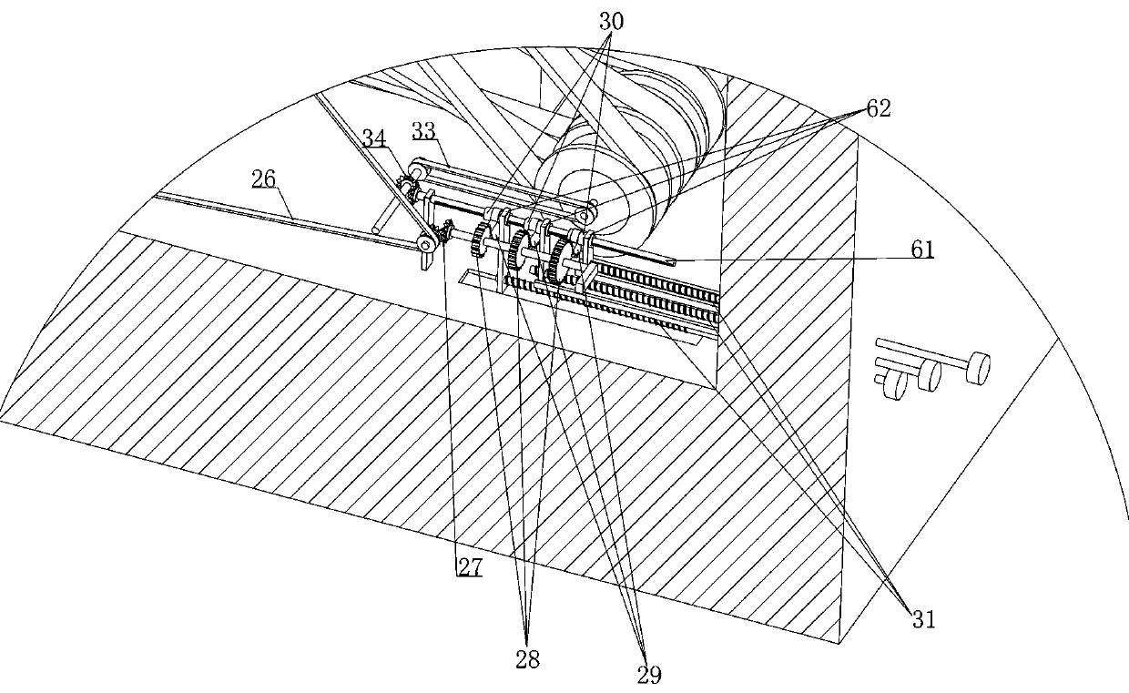
[0049] Embodiment 1, a cervical spine rehabilitation treatment device, including a pillow case 1, is characterized in that a number of rotating shafts 2 are installed in the pillow case 1 and several groups of massage devices are arranged at intervals along the direction of its length extension on the rotating shaft 2 , the rotating shaft 2 is provided with a drive shaft 3 which is installed in the pillow case 1 at intervals with the center of the shaft, and a plurality of rotating shafts 2 are arranged in a stepped distribution in the pillow case 1;
[0050] The massage device includes an arc-shaped plate 4 that is arranged at intervals around the rotating shaft 2 and is slidably fitted along its diameter. The arc-shaped plate 4 is connected with a first transmission device and the first transmission device is driven by the drive shaft 3. The drive The shaft 3 is connected with a reciprocating mechanism arranged in the pillow case 1 and the reciprocating mechanism is connected...
Embodiment 2
[0057] Embodiment 2, on the basis of Embodiment 1, a moxibustion box 9 is provided on the lateral side of the pillow case 1 and the moxibustion box 9 communicates with several of the rotating shafts 2, and the arc-shaped plate 4 is provided with a moxibustion box 9. There is a cavity 10 and a cooling hole 11 is arranged on the outer surface of the arc-shaped plate 4. The cavity 10 communicates with the rotating shaft 2 and a blocking plate 12 is slidably connected in the cavity 10. The blocking plate 12 and the cavity 10 A return spring 13 is connected between one side wall and a trigger lever 14 is fixedly connected to the other side of the blocking plate 12, and the trigger lever 14 protrudes outward from the arc-shaped plate 4. The arc-shaped trigger plate 15 in the box 1, the arc-shaped trigger plate 15 satisfies: when the arc-shaped trigger plate 4 rotates to the position of the arc-shaped trigger plate 15 with the rotating shaft 2, the arc-shaped trigger plate 15 acts on ...
Embodiment 3
[0061] Embodiment 3, on the basis of Embodiment 1, several sliding cylinders 16 are fixedly arranged on the rotating shaft 2 along its diameter direction, and the first transmission device includes an internal thread cylinder axially slidably connected in the sliding cylinder 16 17 and the arc-shaped plate 4 is fixedly connected with the internal thread cylinder 17. The internal thread cylinder 17 is equipped with an external thread cylinder 18 that is rotatably mounted on the inner wall of the rotating shaft 2, and the first bevel gear 19 inherent in the external thread cylinder 18 is located in the massage device of the same group. A plurality of first bevel gears 19 cooperating with each other mesh with a second bevel gear 20 sheathed on the drive shaft 3 .
[0062] When this embodiment is in use, refer to the attached Figure 17 As shown, we are provided with several sliding cylinders 16 along the direction of its diameter extension on the rotating shaft 2, and the arc-sha...
PUM
 Abstract
Description
Claims
Application Information
 - R&D
- Intellectual Property
- Life Sciences
- Materials
- Tech Scout
- Unparalleled Data Quality
- Higher Quality Content
- 60% Fewer Hallucinations
Browse by: Latest US Patents, China's latest patents, Technical Efficacy Thesaurus, Application Domain, Technology Topic, Popular Technical Reports.
© 2025 PatSnap. All rights reserved.Legal|Privacy policy|Modern Slavery Act Transparency Statement|Sitemap|About US| Contact US: help@patsnap.com


