

Virus detection sensor, and device and method for detecting virus concentration
A virus detection and sensor technology, which is applied in the field of virus detection sensors and virus concentration detection devices, can solve the problems of cumbersome implementation process, increased inspection cost, high technical requirements, etc., and achieve simplification of cumbersome operation process, low cost and simplified process flow Effect
- Summary
- Abstract
- Description
- Claims
- Application Information
AI Technical Summary
Problems solved by technology
Method used
Image

Examples
Embodiment 1
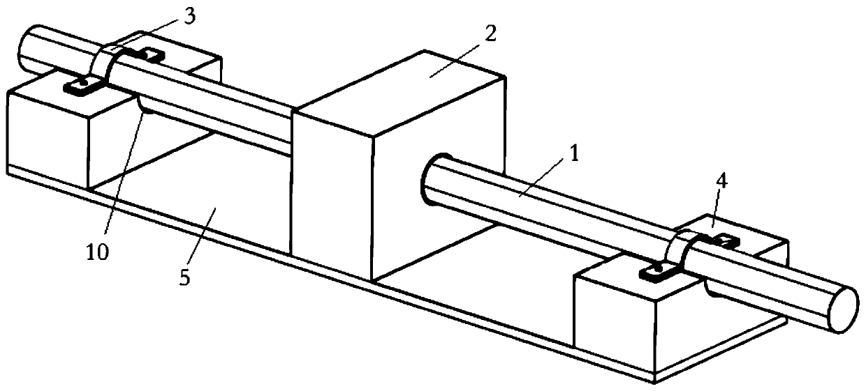
[0054] The structure of the virus detection sensor provided in this embodiment is as follows: figure 1 As shown, including stand, detection probe and capillary glass tube 1.
[0055] The bracket includes a support plate and a clamp, and there are two clamps. The fixture includes a support body 4 and an elastic C-shaped clamp 3. Both the support body 4 and the support plate 5 are square. The support body 4 is symmetrically fixed on one surface of the support plate 5. One side of the two support bodies 4 is respectively connected The boards are close to each other, and there is a symmetrical semicircular third groove 10 on the other side of the two supporting bodies 4 which is parallel to the supporting board 5 and not in contact with it.
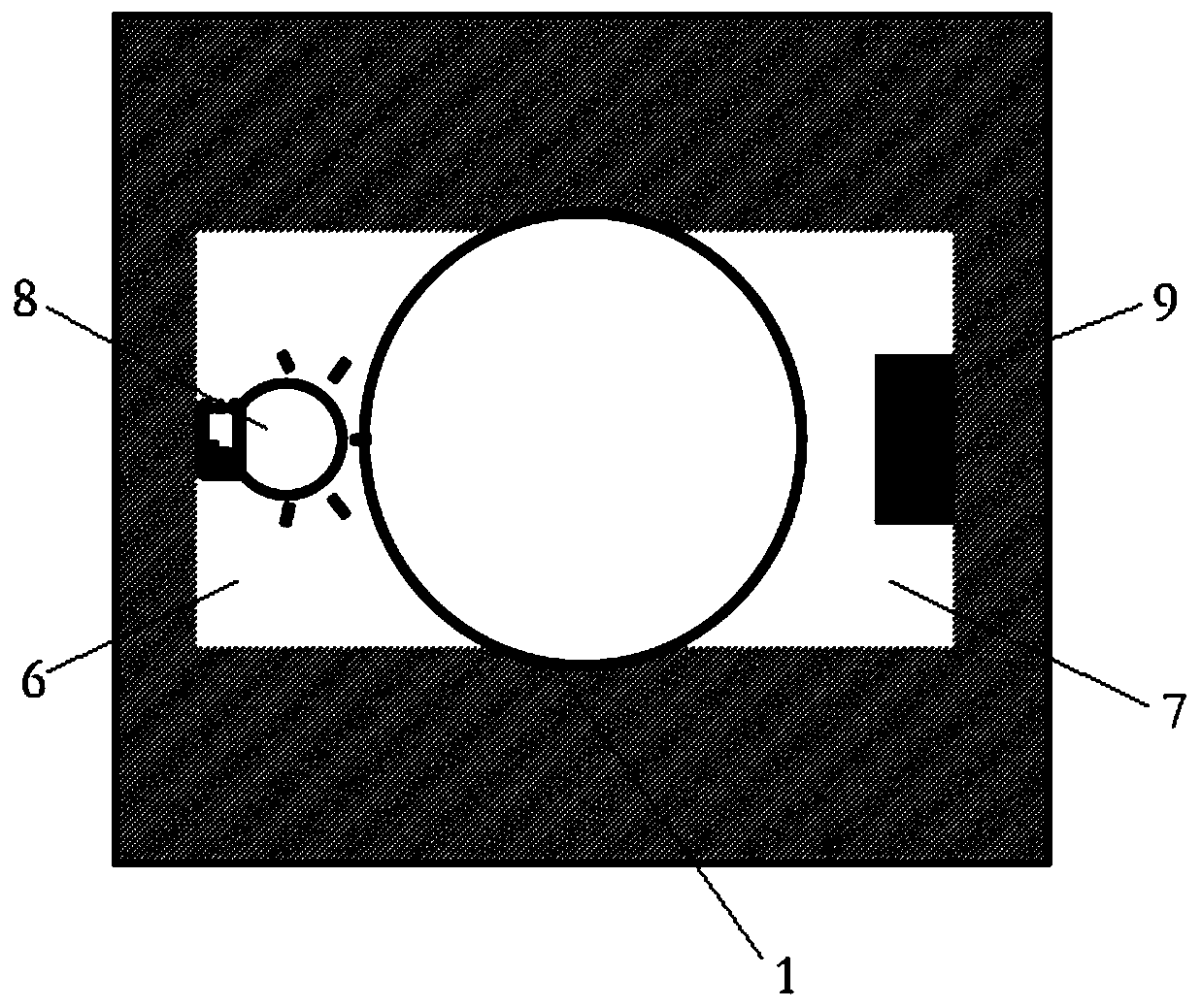
[0056] The detection probe includes a detection body 2 and a photoelectric conversion circuit. The photoelectric conversion circuit includes a photoresistor 9 and a light emitting diode 8 . The detection body 2 is square, the detection bod...
Embodiment 2
[0073] The structure of the device for detecting virus concentration provided by this embodiment is as follows: Figure 4 As shown, it includes the virus detection sensor, power mechanism, valve control mechanism, reagent supply mechanism, magnetic separation mechanism, detection mechanism, first waste liquid bottle 55 and second waste liquid bottle 56 of Embodiment 1.
[0074] The power mechanism includes an air suction pump 11, a first air extraction branch pipe 12, a first valve 13, a second air extraction branch pipe 26 and a second valve 27, and both the first valve 13 and the second valve 27 are electric proportional valves. One end of the first air extraction branch pipe 12 and the second air extraction branch pipe 26 is connected with the outlet of the air pump 11, the first valve 13 is installed on the first air extraction branch pipe 12, and the second valve 27 is installed on the second air extraction branch pipe 26 .
[0075] Reagent supply mechanism comprises the...
Embodiment 3
[0085] 1. Preparation of antibody-modified magnetic sphere suspension:
[0086] 1) Place the EP tube in a Mettler AT20 microbalance and set it to zero, and weigh 4 mg of 10 μg / ml of EDC and 2 mg of 5 μg / ml of NHS with the EP tube;
[0087] 2) Take 20 μL of magnetic nanospheres into the EP tube, then inject PBS buffer solution (PH=6.8) with a pipette gun, rotate and wash on the magnetic stand, and suck out the PBS solution with a pipette gun, and clean the magnetic nanospheres according to this method Three times, after washing, add 400 μL of PBS solution to the EP tube;
[0088] 3) Add EDC and NHS to the EP tube. EDC is insoluble, so add it first, and then place the EP tube in a constant temperature shaker for 30 minutes;
[0089] 4) After shaking, wash three times with PBS buffer solution (PH=7.2) on the magnetic stand to remove excess EDC and NHS powder;
[0090] 5) Add the H7N9 antibody to the EP tube, shake it in a constant temperature shaker for 4 hours, and obtain the ...
PUM
 Abstract
Description
Claims
Application Information