
Moving-out type ultra-fan engine

An engine and removal technology, applied in the direction of machine/engine, jet propulsion, etc., can solve the problem that the fan and the low-pressure turbine cannot reach the optimal speed at the same time, the ADP is difficult to put into practical use, the installation loss increases, etc., to achieve safety. Improved performance, reduced moment of inertia, and reduced exhaust pollution

Inactive Publication Date: 2003-04-16
谢逢申
View PDF8 Cites 0 Cited by
  • Summary
  • Abstract
  • Description
  • Claims
  • Application Information

AI Technical Summary

Problems solved by technology

However, ADP still has the following four technical key points that have not been resolved
[0003] 1. Reducer problem: Due to the large diameter of the ADP fan, the fan must be driven by the low-pressure turbine through the reducer, otherwise the fan and the low-pressure turbine cannot reach their respective optimal speeds at the same time
However, the reliability problem of light weight and high power reducer has not been solved, which is the first key for ADP to put into production
[0004] 2. Weight problem: flutter is the main problem in the work of fan blades
[0005] 3. The problem of installation loss: the diameter of the nacelle increases with the diameter of the fan, and the installation loss increases accordingly, which further offsets the advantage of high duct ratio
[0007] Before the above four key technological breakthroughs, it is difficult for ADP to be put into practical use

Method used


Image

  • Moving-out type ultra-fan engine
  • Moving-out type ultra-fan engine
  • Moving-out type ultra-fan engine

Examples


Embodiment Construction

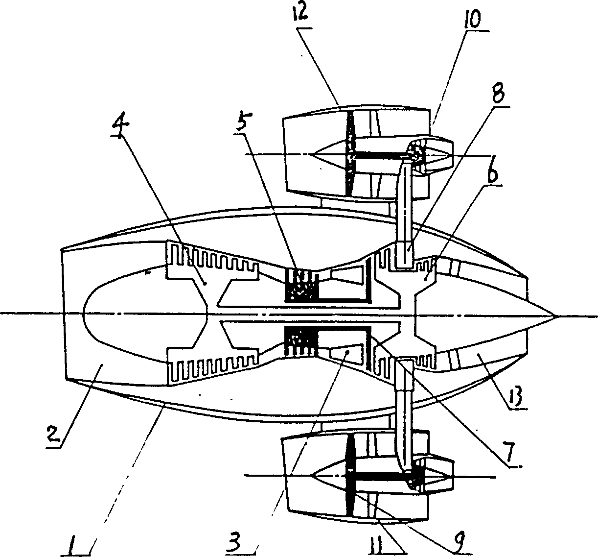
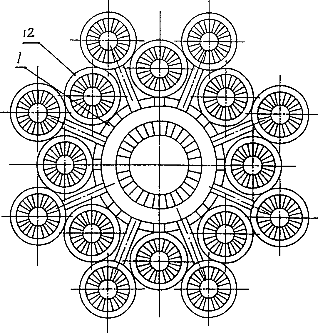
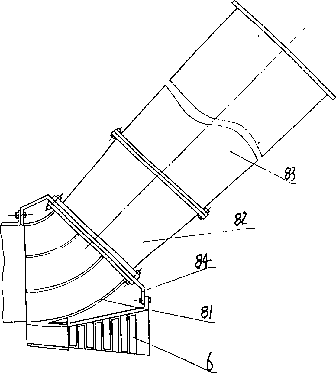
[0027] see figure 1 , figure 2 , the present invention is made up of main engine 1 including air inlet 2, combustion chamber 3, high-pressure compressor 5, low-pressure compressor 4, high-pressure turbine 7, low-pressure turbine 6, tail nozzle 13 and auxiliary turbofan 12. After the first or second stage of the low-pressure turbine 6, a gas splitting device 8 is provided, figure 1 In the middle, a gas distribution device is provided between the second and third stages, and a total of 16 auxiliary turbines 10 connected with the gas distribution device 8 are arranged around the main engine 1, and each auxiliary turbine 10 is used to drive a small fan 9, forming The auxiliary turbofan 12 is located in the nacelle 11 and bound around the main engine 1 . The structure of the gas splitting device 8 of the present invention is as image 3 As shown, it is composed of a flow divider 81, a flow confluence 82 and a flow divider (i.e., a diffuser) 83. The flow divider 81 is a thin-wal...


PUM


Abstract

The present invention relates to a civil aviation jet engine, in particular, it is an out-shifted hyperfan engine. The existent technical structure of its main engine is composed of inlet duct, high and low pressure compressors, combustion chamber, high and low pressure turbines and tail pipe. Said invention is characterized by that its fan is shifted out and substituted by several small fans, and each small fan is driven by auxiliary turbine, and its low pressure turbine is equipped with a gas divider device for driving auxiliary turbine. Said invention removes decelerator, and solves four key problems of existent ADP, so that it opens up a bright vista for practical application of ultra-high by-pass ratio engine.

Description

technical field [0001] The invention relates to a civil aviation jet engine, in particular to a removable superfan engine. Background technique [0002] Civil aviation jet engine has experienced three generations since its advent, and the fourth generation is currently being developed. The fourth generation is ultra-high bypass ratio turbofan engine, which can be divided into two categories, one is paddle fan engine with a bypass ratio of 30-50; the other is superfan engine with a bypass ratio of 10-20. The propfan engine has received the most worldwide attention, but due to unresolved noise and installation problems, development has been stopped. Among the superfan engines, ADP (Advanced ducted Prop) developed by Pratt & whitney of the United States has made rapid progress. Its performance: reduced fuel consumption, increased thrust, reduced noise and exhaust pollution have been confirmed. However, ADP still has the following four key technical issues that have not been r...

Claims


Application Information

Patent Timeline
Patent Type & Authority Patents(China)
IPC IPC(8): F02K3/04
Inventor 谢逢申
Owner 谢逢申
Learn More