Reeled yarn unwinding device

A technology of unwinding device and hank, applied in the field of hank unwinding device and spinning machinery components, can solve the problems of too large or too small, broken or loose, difficult to take yarn, etc. The effect of loose thread, easy yarn removal and simple structure

Active Publication Date: 2019-12-20
海盐县梦芝舟毛纺厂
View PDF10 Cites 0 Cited by
  • Summary
  • Abstract
  • Description
  • Claims
  • Application Information

AI Technical Summary

Problems solved by technology

[0002] The speed control of the existing skein rack driving device generally monitors the tension of the skein through the tension sensor. When the tension value of the skein exceeds the specified value, the tension sensor sends a signal to the controller, and the controller controls the speed of the driving device. Increase, when the tension value of the skein yarn is less than the specified value, the tension sensor sends a signal to the controller, and the controller controls the speed of the driving device to decrease. However, the above-mentioned tension sensor has a monitoring hysteresis factor. value, the tension value at this time is too large or too small, plus the system response time, it is still easy to break or loosen the thread
[0003] The outer diameter of the existing hank creel is fixed, and it is necessary to use a hank creel of different diameters for different yarns or requirements. Therefore, a large number of hank creels are stored in spinning enterprises, occupying a large area. Space, especially due to the fixed outer diameter of the gallows, in the process of completing the skein, it is difficult to take the yarn due to the effect of the yarn pre-tightening force during the yarn taking process

Method used


Image

  • Reeled yarn unwinding device
  • Reeled yarn unwinding device
  • Reeled yarn unwinding device

Examples


Embodiment Construction

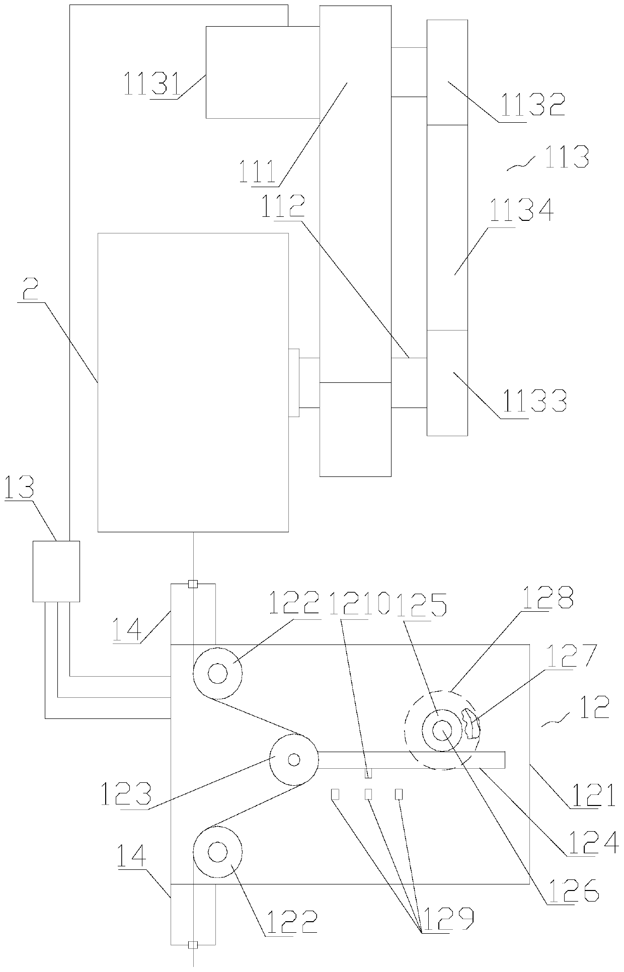
[0025] refer to figure 1 , figure 2 and image 3, a skein unwinding device of the present invention comprises a driving mechanism 11, a tension monitoring mechanism 12 located below the driving mechanism 11, a controller 13 and a skein scaffold 2, and the driving mechanism 11 and the tension monitoring mechanism 12 are all connected with the control device 13, the driving mechanism 11 is provided with a skein scaffolding 2, and the tension monitoring mechanism 12 includes a mounting seat 121, two fixed guide wheels 122, a moving guide wheel 123, a sliding rack 124, a driving gear 125, Drive shaft 126, constant force clockwork spring I127, housing 128, three inductors 129 and induced body 1210, the outside of described mounting seat 121 is provided with two fixed guide wheels 122 and the sliding tooth bar 124 that can be slidably installed, The front end of the sliding rack 124 is provided behind the middle of the two fixed guide wheels 122, and the outer side of the mountin...


PUM


Abstract

The invention discloses a reeled yarn unwinding device. The reeled yarn unwinding device comprises a drive mechanism, a tension monitoring mechanism located below the drive mechanism, a controller anda reeled yarn shed frame. The drive mechanism and the tension monitoring mechanism are connected with the controller. The reeled yarn shed frame is arranged on the drive mechanism. The tension monitoring mechanism comprises a mounting seat, two fixed guide wheels, a moving guide wheel, a sliding gear rack, a drive gear, a drive shaft, a constant-force spring I, an outer shell, three inductors andan inducted body. The two fixed guide wheels and the sliding gear rack capable of being mounted in a sliding manner are arranged on the outer side of the mounting seat. Compared with the prior art, the phenomenon of breaking or loosening can be greatly reduced, the structure is simple, constant-force tensioning is achieved, yarn can be taken easily, the peripheral diameter can be adjusted, and adjusting is convenient and rapid.

Description

【Technical field】 [0001] The invention relates to the technical field of spinning machinery components, in particular to the technical field of a skein unwinding device. 【Background technique】 [0002] The speed control of the existing skein rack driving device generally monitors the tension of the skein through the tension sensor. When the tension value of the skein exceeds the specified value, the tension sensor sends a signal to the controller, and the controller controls the speed of the driving device. Increase, when the tension value of the skein is less than the specified value, the tension sensor sends a signal to the controller, and the controller controls the speed of the driving device to decrease. However, the above-mentioned tension sensor has a monitoring hysteresis factor. value, the tension value at this time is too large or too small, plus the system response time, it is still easy to break or loose the thread. [0003] The outer diameter of the existing ha...

Claims


Application Information

Patent Timeline
Patent Type & Authority Applications(China)
IPC IPC(8): B65H49/20B65H59/38B65H57/14B65H63/02
CPCB65H49/20B65H57/14B65H59/387B65H63/02B65H2701/31
Inventor 缪会君
Owner 海盐县梦芝舟毛纺厂
Why Eureka
Try Eureka