Novel floor for floor heating
A geothermal floor, a new type of technology, applied in the direction of elastic floor, floor, covering/lining, etc., to achieve the effect of low drying requirements, high thermal conductivity, and energy saving and consumption reduction
- Summary
- Abstract
- Description
- Claims
- Application Information
AI Technical Summary
Problems solved by technology
Method used
Image
Examples
Embodiment 1
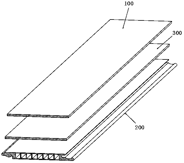
[0037] Example 1: Reference figure 1A new type of geothermal floor shown includes a decorative layer 100 and a base material layer 200 that are glued to each other. Wherein, the decorative layer 100 is a hardwood material layer, such as oak veneer with a thickness of 0.1mm-5.0mm, preferably, the thickness is 2.0mm-3.0mm; the base material layer 200 is a metal material layer, such as an integrally formed aluminum alloy substrate. The decoration layer 100 and the base layer 200 are bonded and bonded by thermosetting glue or cold-setting glue, for example, polyurethane glue, water-based glue and the like. The total thickness of this new type of geothermal floor is 6mm-22mm, and a locking structure is formed around the body.
[0038] In this embodiment, the part of the substrate layer 200 used to form the locking structure is a solid structure, and the locking structure is formed by milling, while the other part (main part) of the substrate layer 200 is a hollow structure.
[0...
Embodiment 2
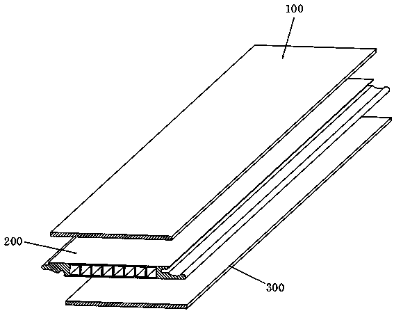
[0040] Embodiment 2: the difference between embodiment 2 and embodiment 1 is that reference figure 2 As shown, the buffer layer 300 is disposed on the bottom surface of the base material layer 200 , and its bonding method to the bottom surface of the base material layer 200 is the same as that in Embodiment 1.
Embodiment 3
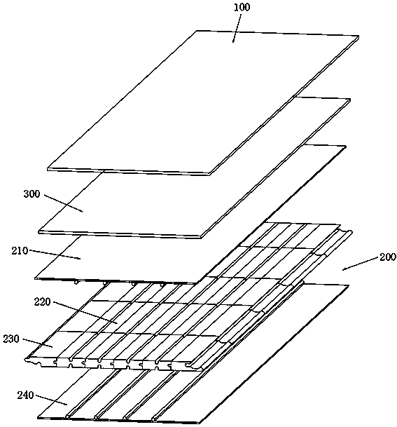
[0041] Embodiment 3: the difference between embodiment 3 and embodiment 1 is that, refer to image 3 As shown, the substrate layer 200 is a split structure. The base material layer 200 includes an adhesive connection structure 210 on the bottom surface of the decoration layer 100 , and a support module 220 fixed on the bottom surface of the connection structure 210 by clamping. The support module 220 is composed of a plurality of support units 221 that are clamped and connected to each other; the plurality of support units 221 form 2-6 rows (preferably 3 or 4 rows) of support units 221 in the width direction. 8-16 rows (preferably 10-12 rows) of supporting monomers 221 are formed in the direction.
[0042] refer to Figure 4 As shown, the connecting structure 210 includes a connecting plate 211, a first clamping member 212 fixed on the back of the connecting plate 211, a locking module 300 fixed on the surrounding sides of the support module 220 by clamping, and a locking mo...
PUM
| Property | Measurement | Unit |
|---|---|---|
| Thickness | aaaaa | aaaaa |
| Thickness | aaaaa | aaaaa |
Abstract
Description
Claims
Application Information
 - R&D
- Intellectual Property
- Life Sciences
- Materials
- Tech Scout
- Unparalleled Data Quality
- Higher Quality Content
- 60% Fewer Hallucinations
Browse by: Latest US Patents, China's latest patents, Technical Efficacy Thesaurus, Application Domain, Technology Topic, Popular Technical Reports.
© 2025 PatSnap. All rights reserved.Legal|Privacy policy|Modern Slavery Act Transparency Statement|Sitemap|About US| Contact US: help@patsnap.com


