
Drying device for electronic equipment optical component research and development

A technology of electronic equipment and drying device, applied in the direction of drying gas arrangement, heating device, drying solid materials, etc., can solve the problems of low drying degree and low drying efficiency, achieve fast drying speed, improve drying speed, and energy cycle The effect of using

Inactive Publication Date: 2019-12-20
扬州辰亚光学科技有限公司
View PDF7 Cites 1 Cited by
  • Summary
  • Abstract
  • Description
  • Claims
  • Application Information

AI Technical Summary

Problems solved by technology

In the process of optical instrument processing, processes such as cutting, grinding, cleaning and drying are required. Traditional drying devices have low drying efficiency and a low degree of drying thoroughness. If thorough drying is required, a lot of energy and time are required

Method used


Image

  • Drying device for electronic equipment optical component research and development
  • Drying device for electronic equipment optical component research and development
  • Drying device for electronic equipment optical component research and development

Examples


Embodiment Construction

[0020] The following will clearly and completely describe the technical solutions in the embodiments of the present invention with reference to the accompanying drawings in the embodiments of the present invention. Obviously, the described embodiments are only some, not all, embodiments of the present invention. Based on the embodiments of the present invention, all other embodiments obtained by persons of ordinary skill in the art without making creative efforts belong to the protection scope of the present invention.

[0021] Unless otherwise defined separately, directions such as up, down, left, right, front, back, inside and outside referred to herein are up, down, left, right, front and back in the drawings shown in the present invention. , inside and outside directions shall prevail, which shall be explained together here.

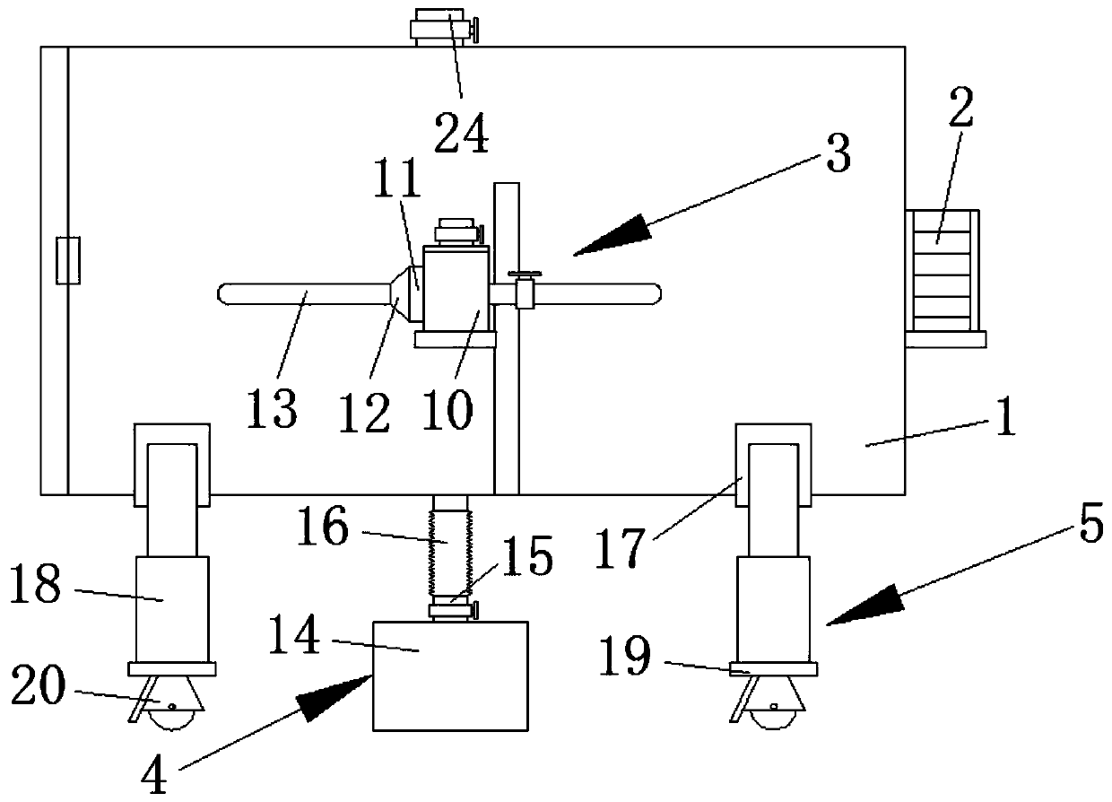
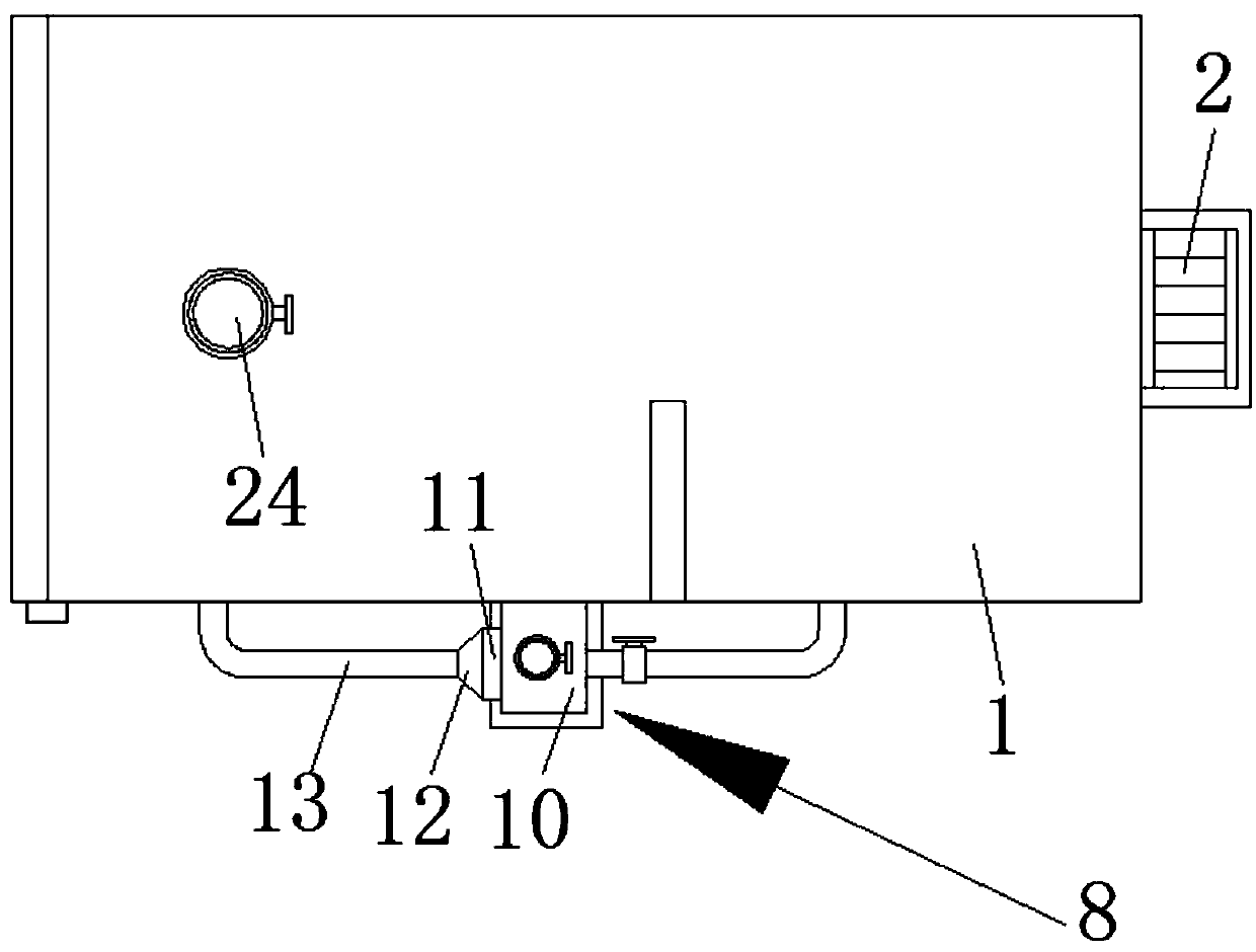
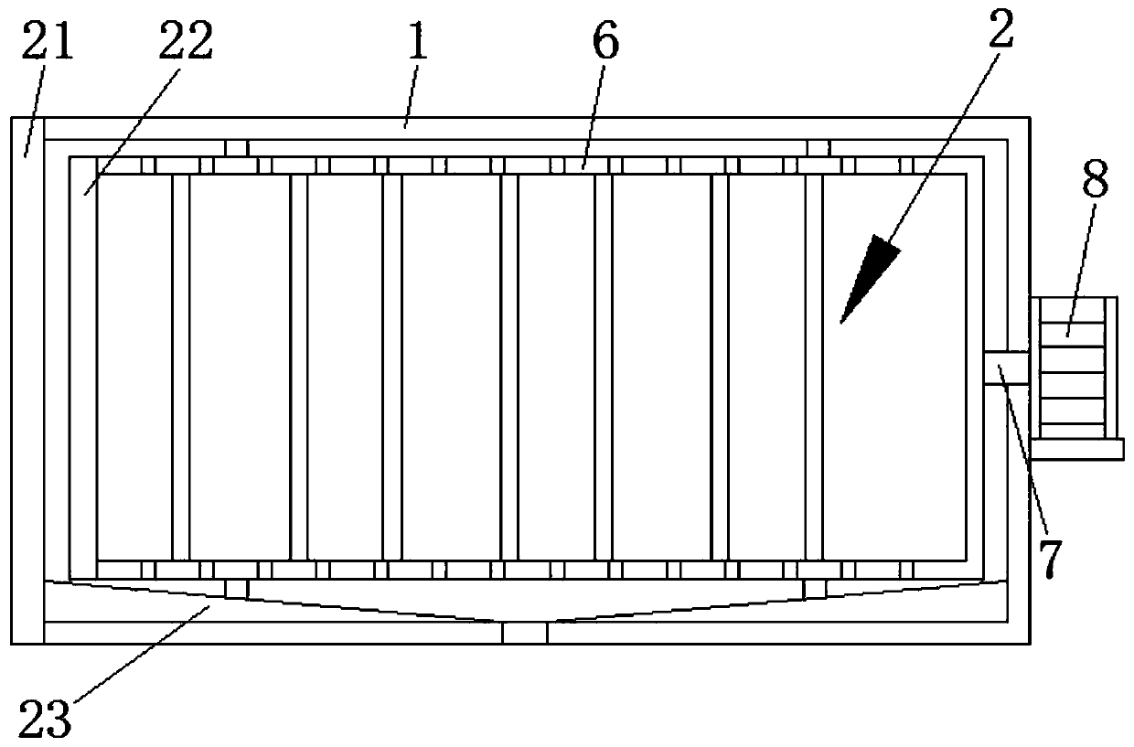
[0022] The present invention provides such Figure 1-5 The shown drying device for researching and developing optical parts of electronic equipment...


PUM


Abstract

The invention discloses a drying device for electronic equipment optical component research and development. The drying device for electronic equipment optical component research and development comprises a drying bucket, a stirring device, a heating device, a water receiving device and adjustment devices, wherein the stirring device is arranged in an inner cavity of the drying bucket; a stirringbucket of the stirring device is rotationally connected with the drying bucket through two groups of bearing seats which are welded to the periphery; the heating device is communicated to the side surface of the drying bucket; the water receiving device is communicated to the bottom end of the drying bucket; two adjustment devices which are arranged side by side are welded to the bottom end of thedrying bucket; a perspective window is bonded onto the inner wall of a perspective groove which is excavated in the front end of the drying bucket through adhesive; the stirring device comprises thestirring bucket, a rotary shaft and a rotary motor; a rubber pad used for protecting is bonded onto the inner wall of the stirring bucket through adhesive; and a plurality of groups of equidistantly-arrayed rubber columns used for protecting and blocking are further bonded onto the inner wall of the stirring bucket through adhesive. The drying device for electronic equipment optical component research and development is high in drying speed, and capable of cyclically utilizing energy.

Description

technical field [0001] The invention belongs to the technical field of parts drying, and in particular relates to a research and development drying device for optical parts of electronic equipment. Background technique [0002] Optical instruments are composed of single or multiple optical devices. Optical instruments are mainly divided into two categories, one is optical instruments that form real images, such as slide projectors, cameras, etc.; the other is optical instruments that form virtual images, such as telescopes, microscopes, magnifying glasses, etc. Optical instruments are a very important component category in the instrumentation industry, and are indispensable tools for observation, testing, analysis, control, recording and transmission in various fields of industrial and agricultural production, resource exploration, space exploration, scientific experiments, national defense construction and social life . In particular, the functions of modern optical instr...

Claims


Application Information

Patent Timeline
Patent Type & Authority Applications(China)
IPC IPC(8): F26B11/04F26B21/00F26B23/00F26B25/00F26B25/04F26B25/12F26B25/16
CPCF26B11/04F26B21/001F26B21/004F26B23/00F26B25/00F26B25/003F26B25/04F26B25/12F26B25/16
Inventor 戚志洋
Owner 扬州辰亚光学科技有限公司
Learn More