
High-temperature fluid quantitative discharging system and high-temperature fluid quantitative discharging method

A technology of high-temperature fluid and quantitative discharge, which is applied in fixed measuring chambers and other directions

Active Publication Date: 2019-12-20
SHANGHAI INST OF APPLIED PHYSICS - CHINESE ACAD OF SCI
View PDF6 Cites 0 Cited by
  • Summary
  • Abstract
  • Description
  • Claims
  • Application Information

AI Technical Summary

Problems solved by technology

[0006] The technical problem to be solved by the present invention is to overcome the defect in the prior art that lacks a device that can be used to accurately and quantitatively take out a small amount of high-temperature fluid medium in a closed large-diameter container multiple times, and provides a high-temperature fluid quantitative Discharge system and discharge method

Method used


Image

  • High-temperature fluid quantitative discharging system and high-temperature fluid quantitative discharging method

Examples


Embodiment 1

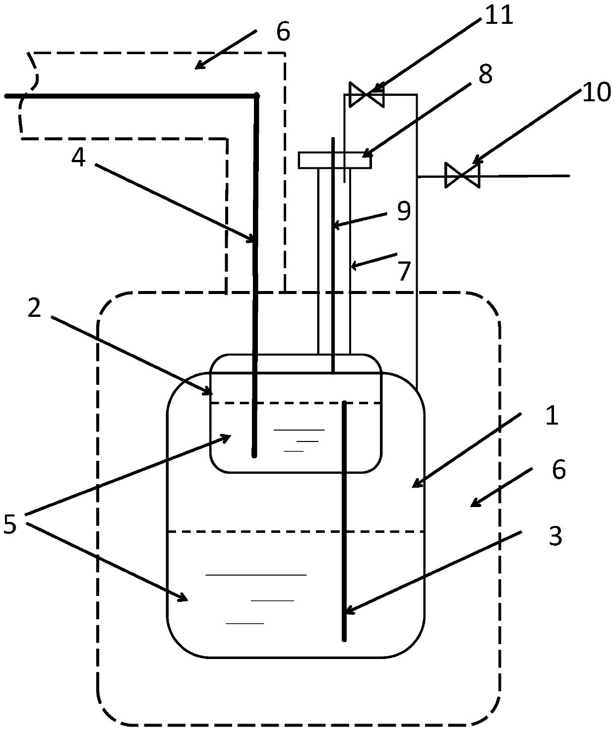
[0060] The high-temperature fluid quantitative discharge system provided in this embodiment is as follows: figure 1 shown. It includes a first container 1, a second container 2 and a gas system, the first container 1 and the second container 2 are airtight containers, the second container 2 is set above the first container 1, and the second container 2 The inner diameter is smaller than the inner diameter of the first container 1; the bottom surface of the second container 2 is vertically sealed with a first conduit 3, the top of the first conduit 3 extends into the middle and upper part of the inner cavity of the second container 2, and the bottom end extends into the inner cavity of the second container 2. The bottom of the inner cavity of the first container 1; The top surface of the second container 2 is also vertically sealed with a second conduit 4, and the bottom end of the second conduit 4 stretches into the bottom of the inner cavity of the second container 2; The sec...


PUM

PropertyMeasurementUnit
The inside diameter ofaaaaaaaaaa
Melting pointaaaaaaaaaa

Abstract

The invention discloses a high-temperature fluid quantitative discharging system and a high-temperature fluid quantitative discharging method. The high-temperature fluid quantitative discharging system comprises a first container, a second container and a gas path system, wherein the second container is arranged above the first container, and the inner diameter of the second container is smaller than that of the first container; a first guide pipe is vertically arranged on the bottom surface of the second container in a penetrated mode, the top end of the first guide pipe stretches into the middle upper part of the inner cavity of the second container, and the bottom end of the first guide pipe stretches into the bottom of the inner cavity of the first container; a second guide pipe is arranged on the top surface of the second container in the penetrated mode, and the bottom end of the second guide pipe stretches into the bottom of the inner cavity of the second container; a thermocouple is arranged on the top surface of the second container in the penetrated mode, and the bottom end of the thermocouple stretches into the inner cavity of the second container and is higher than thetop end of the first guide pipe by more than 2 cm; the gas path system comprises a pressurizing or depressurizing system which enables the first container and the second container to form a pressure difference and enables the second container and the top end outlet of the second guide pipe to form a pressure difference, and a connection system which can realize the air pressure balance of the first container and the second container. The discharging system is accurate in quantification; the system can be repeatedly used for many times, is high in quantitative repeatability, and can not cause material loss; the sealing performance is good, and the material is ensured not to be in contact with air.

Description

technical field [0001] The invention relates to a high-temperature fluid quantitative discharge system and a discharge method. Background technique [0002] In the fields of comprehensive utilization of thermal energy, nuclear energy, chemical industry, etc., it is necessary to accurately and quantitatively take out a small amount of high-temperature fluid medium (such as molten salt) from a closed container with a large inner diameter without contact with air, and use it in the form of flow Transferred to another application, at the same time, the high temperature fluid medium does not produce quantitative losses. [0003] If the sampling volume is less than 100mL each time, it can be taken out by passing the sampling capsule through a closed sampling channel of comparable size, but the taking out process takes a long time, and it is difficult to maintain the liquid state after taking out. If the sampling volume exceeds 100mL, especially between 500mL and 10L, it is diffic...

Claims


Application Information

Patent Timeline
IPC IPC(8): G01F11/28
CPCG01F11/28
Inventor 汤睿谢雷东赵素芳王建强赵乾坤傅杰申淼
Owner SHANGHAI INST OF APPLIED PHYSICS - CHINESE ACAD OF SCI
Learn More