Antenna test method using unmanned aerial vehicle and differential GNSS positioning

A test method, technology of unmanned aerial vehicles, applied in the direction of radio wave measurement system, satellite radio beacon positioning system, antenna radiation pattern, etc.

Inactive Publication Date: 2019-12-20
NORTHWESTERN POLYTECHNICAL UNIV
View PDF12 Cites 5 Cited by
  • Summary
  • Abstract
  • Description
  • Claims
  • Application Information

AI Technical Summary

Problems solved by technology

[0004] In order to overcome the current problem of measurement accuracy caused by inaccurate positioning of drones, the present invention provides an antenna measurement method using small multi-rotor drones and differential GNSS positioning control

Method used


Image

  • Antenna test method using unmanned aerial vehicle and differential GNSS positioning
  • Antenna test method using unmanned aerial vehicle and differential GNSS positioning
  • Antenna test method using unmanned aerial vehicle and differential GNSS positioning

Examples


Embodiment 1

[0063] 1. Load the signal source and transmitting antenna on the UAV

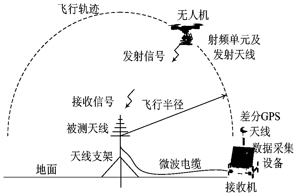
[0064] refer to figure 1 , using a small quadrotor UAV to measure a logarithmic periodic antenna with a test frequency of 1GHz. The signal source generates a continuous wave signal. In order to increase the signal strength, a power amplifier is connected to the back end of the signal source. The power amplifier is connected to the transmitting antenna. The transmitting antenna is a dipole antenna. All three are installed on the UAV. The signal source and power amplifier are powered, and the signal is transmitted through the transmitting antenna. The antenna under test receives the signal and transmits it to the receiver through the microwave cable, and the data acquisition equipment acquires the data of the receiver. The UAV flies a vertical semicircular trajectory around the antenna under test, and the UAV ground station records the flight trajectory of the UAV. The flight radius of the UAV is 4m, which...


PUM


Abstract

The invention relates to an antenna test method using an unmanned aerial vehicle and differential GNSS positioning. A signal source and a transmitting antenna are carried on a small multi-rotor unmanned aerial vehicle as a transmitting source; and the transmitting antenna pattern is considered to be affected by the unmanned aerial vehicle body. The unmanned aerial vehicle flies according to a preset trajectory; the antenna to be tested receives the transmitting signal during the flight; the power of the signal received by the antenna to be tested is collected at a certain time interval througha spectrum analyzer; and the gain pattern of the antenna to be tested is obtained by using the power of the received signal. In order to make the unmanned aerial vehicle fly accurately according to the preset trajectory, the real-time differential GPS positioning is used as navigation information, and the flight trajectory of the unmanned aerial vehicle is accurately controlled through a geometric control method.

Description

technical field [0001] The invention relates to a method for antenna testing by using differential GNSS positioning to accurately control the flight trajectory of an unmanned aerial vehicle, and belongs to the field of antenna measurement. Background technique [0002] The patent "Antenna Far-Field Measurement Method Based on UAV, CN109061322A, China" provides a UAV-based antenna far-field measurement method. This method uses a UAV carrying a transmitter to fly in the far-field area according to the planned route. The signal transmitter sends signal strength information to the antenna under test in real time. The signal strength information is matched with the position information corresponding to the signal strength information, so as to obtain the far field information of the relative spatial position of the antenna to be tested. The method described in this patent mainly uses the GPS system of the UAV for positioning, and the position error of the flight trajectory may r...

Claims


Application Information

Patent Timeline
Patent Type & Authority Applications(China)
IPC IPC(8): G01R29/10G05D1/10G01S19/42
CPCG01R29/10G01S19/42G05D1/101
Inventor 胡楚锋马松辉芦永超刘可佳刘宁陈卫军
Owner NORTHWESTERN POLYTECHNICAL UNIV
Why Eureka
Try Eureka