Fan-type gas circulation high repetition frequency Raman cell

A gas circulation and high repetition rate technology, applied in the laser field, can solve the problems of reducing beam power density and Raman gain, Stokes beam quality deterioration, and Raman conversion efficiency decline, etc., to achieve high pump energy, The effect of not being easily damaged and reducing the cooling time

Inactive Publication Date: 2019-12-20
DALIAN INST OF CHEM PHYSICS CHINESE ACAD OF SCI
View PDF5 Cites 0 Cited by
  • Summary
  • Abstract
  • Description
  • Claims
  • Application Information

AI Technical Summary

Problems solved by technology

[0004] The thermal defocusing effect often causes divergence and even distortion of various beams (including pump light and Stokes light) in the SRS; thereby reducing the beam power density and Raman gain, reducing the Raman conversion efficiency, and causing Stokes beam quality degrades, so removing thermal defocusing effects is important for Raman conversion

Method used


Image

  • Fan-type gas circulation high repetition frequency Raman cell
  • Fan-type gas circulation high repetition frequency Raman cell

Examples


Embodiment 1

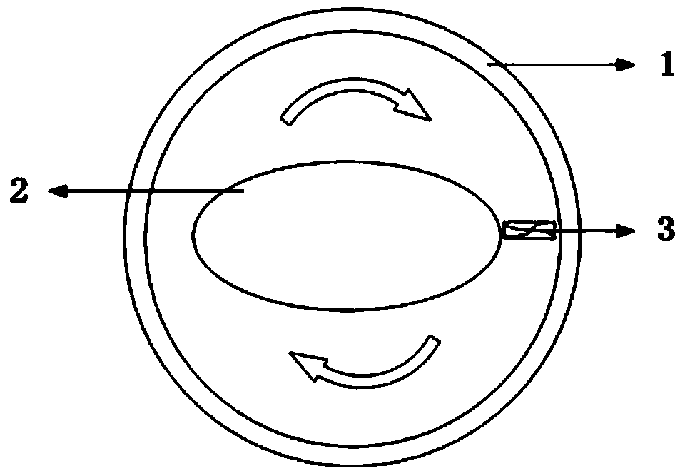
[0034] First, a Raman cell wall with a circular cross section and a filler with an elliptical cross section are used. Place the three-dimensional filler with an elliptical cross-section in the Raman cell, and the position is coaxial with the Raman cell. Adjust the filler or the Raman cell appropriately so that the specifications and sizes of the formed narrow channels are the same, and the formed wide channels The specifications and sizes are the same, and the maximum spacing length between the filler and the Raman cell wall is twice the minimum spacing length. One of the narrow passages is equipped with a row of electric fans, and the other narrow passage is used as a light passage.

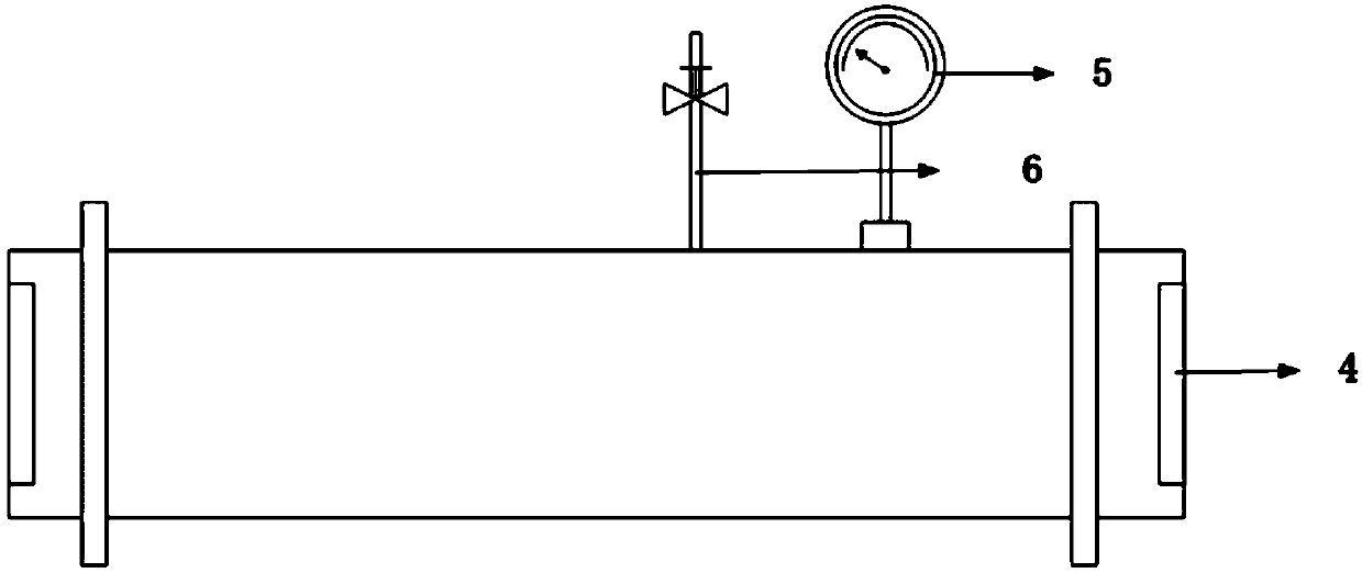
[0035]Fill the Raman cell with sufficient gas medium (the gas should be replaced several times for the first time to ensure the purity of the gas in the Raman cell), adjust the ventilation valve to the required air pressure, and then run the fan group in the Raman cell to stabilize the internal ...

Embodiment 2

[0037] First, a Raman cell wall with a circular cross-section and a filler with an equilateral triangle cross-section are used. Place the three-dimensional filler with an equilateral triangle cross section in the Raman cell, the position is coaxial with the Raman cell, and adjust the filler or the Raman cell appropriately so that the specifications and sizes of the formed narrow channels are the same, and the width of each formed channel is the same. The channel dimensions are the same, and the maximum gap length between the filler and the Raman cell wall is three times the minimum gap length. One of the narrow passages is equipped with a row of electric fan groups, and one of the remaining narrow passages is selected as a light passage.

[0038] Fill the Raman cell with sufficient gas medium (the gas should be replaced several times for the first time to ensure the purity of the gas in the Raman cell), adjust the ventilation valve to the required air pressure, and then run th...


PUM


Abstract

The invention discloses a novel Raman cell capable of reducing the thermal lens effect of high repetition frequency pump light during a gaseous medium propagation process. In the design, the outermostRaman cell wall is made of stainless steel, and a three-dimensional filler is disposed in the Raman cell. Gaps between the outer wall of the Raman cell and the built-in filler can be filled with a high-pressure gas, and have inconsistent widths. A fan unit is placed in one of narrow gaps. One of the remaining narrow gaps is selected as a light passage of the pump light. When high repetition frequency pump light is configured to pump a gaseous medium, the heat in the vicinity of the pump light gradually accumulates and generates a thermal lens effect to affect the beam quality of the output light. After an electric fan operates, the high-pressure gaseous medium in the gaps flows in a fixed direction, takes away the heat in the vicinity of the pump light, reduces the thermal lens effect inthe Raman cell so as to improve the conversion efficiency of Raman light. The novel Raman cell improves the Raman light conversion efficiency and beam quality by reducing the thermal effect, and has bright application prospects.

Description

technical field [0001] The invention belongs to the field of laser technology, and is a fan-type gas circulation Raman cell. The fan inside the Raman cell can make the high-pressure gas flow quickly according to a fixed flow direction, reduce the thermal effect in the Raman cell, and is a method for improving Raman light conversion. method for efficiency and beam quality. The invention can be applied in some fields such as basic scientific research, laser frequency conversion, widening spectrum range, gas concentration detection and the like. [0002] technical background [0003] In the stimulated Raman (stimulated Raman scattering, SRS) process, every time a Stokes photon is generated, a vibrational excited state particle will be generated, and these excited state particles will release a lot of heat when they relax back to the ground state through collisions; For gaseous Raman media, these released heat will cause them to form a negative temperature gradient and positive ...

Claims


Application Information

Patent Timeline
Patent Type & Authority Applications(China)
IPC IPC(8): H01S3/30H01S3/108H01S3/04
CPCH01S3/0404H01S3/1086H01S3/30
Inventor 郭敬为李仲慧蔡向龙刘金波
Owner DALIAN INST OF CHEM PHYSICS CHINESE ACAD OF SCI
Why Eureka
Try Eureka