Hematodialysis conversion device for clinical use in nephrology department

A technology of hemodialysis and switching devices, which is applied in the clinical field of nephrology. It can solve the problems of cumbersome and complicated operation of drainage fluid flow control and difficult switching and adjustment of outlet tube flow, and achieve simple and fast switching and adjustment, ensuring stability and convenient use. Effect

Pending Publication Date: 2019-12-24
董燕娇
View PDF0 Cites 0 Cited by
  • Summary
  • Abstract
  • Description
  • Claims
  • Application Information

AI Technical Summary

Problems solved by technology

However, the flow rate of the outlet pipe on the existing dialysis conversion head is difficult to switch and adjust, which makes people's control of the flow rate of the drainage fluid complicated and

Method used


Image

  • Hematodialysis conversion device for clinical use in nephrology department
  • Hematodialysis conversion device for clinical use in nephrology department
  • Hematodialysis conversion device for clinical use in nephrology department

Examples


Embodiment 1

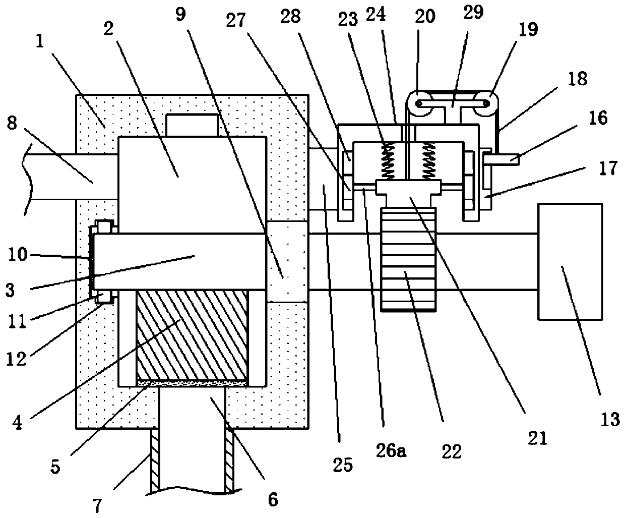
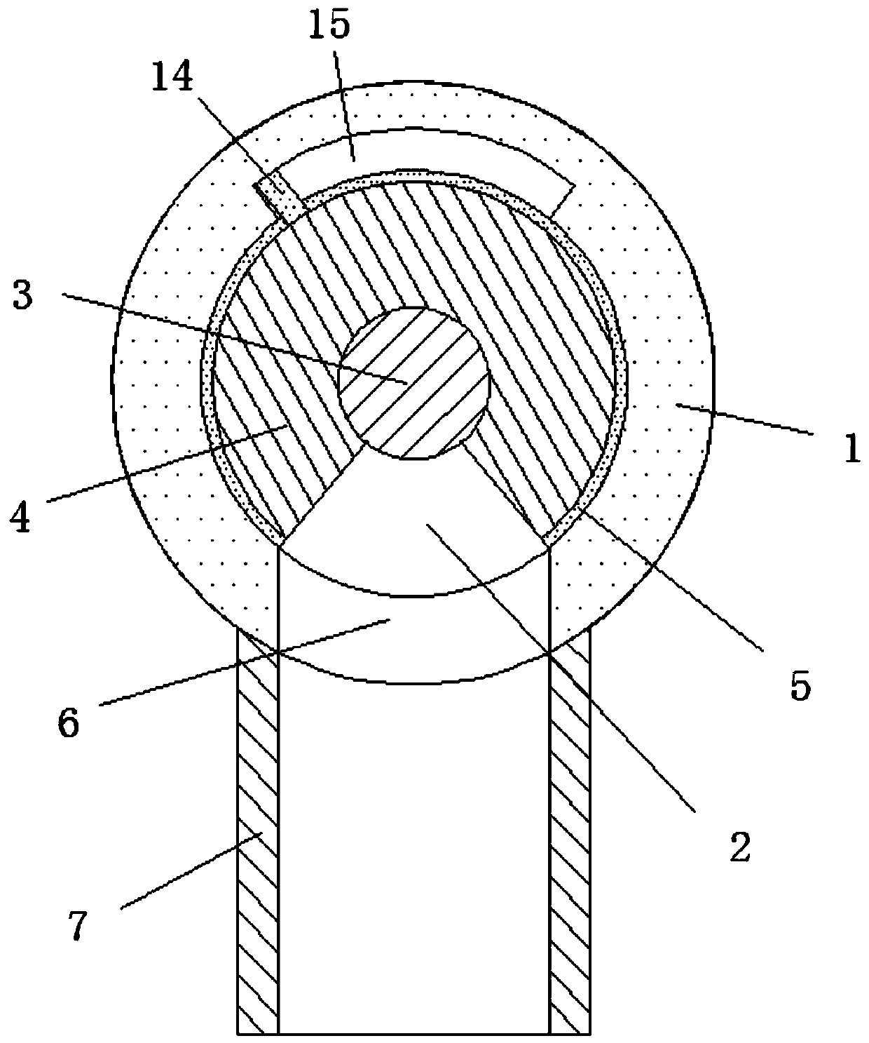
[0027] refer to figure 1 , 2 , 3. In this embodiment, a hemodialysis conversion device for clinical nephrology is proposed, including a conversion head 1, a cylindrical cavity 2 is provided inside the conversion head 1, and a rotating shaft is installed in the cylindrical cavity 2 3. A conversion adjustment block 4 is fixedly sleeved on the rotating shaft 3, and the conversion adjustment block 4 is an arc-shaped structure. A sealing gasket 5 is fixedly arranged on the arc-shaped outer wall of the conversion adjustment block 4, and the conversion adjustment block 4 is The sealing gasket 5 is in sealing and sliding connection with the arc-shaped inner wall of the cylindrical cavity 2, and the bottom inner wall of the cylindrical cavity 2 is provided with a liquid outlet hole 6, and the flow rate of the conversion adjustment block 4 to the liquid outlet hole 6 through the sealing gasket 5 The opening is rotated and adjusted to match. The bottom of the conversion head 1 is provid...

Embodiment 2

[0037] Please refer to Figure 4 , 5 , 6, the difference between embodiment two and embodiment one is:

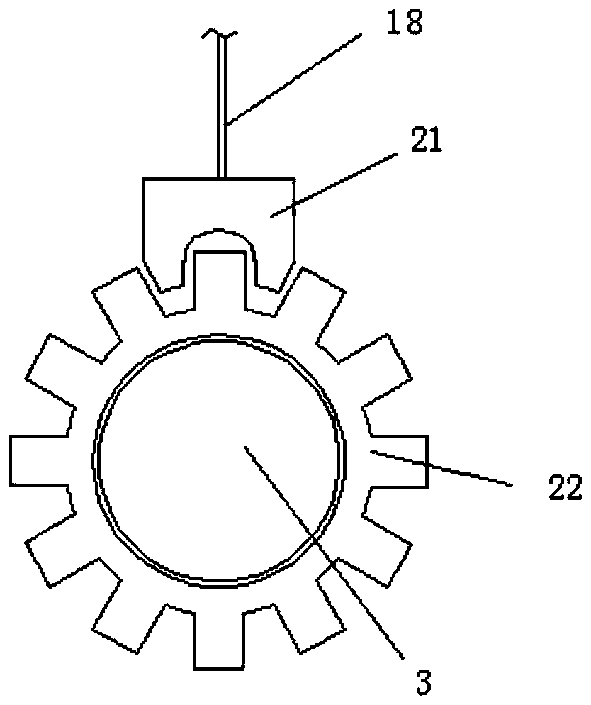
[0038] In the second embodiment, both sides of the locking chuck 21 are fixedly connected with rotating rods 26b, and the ends of the two rotating rods 26b away from each other are respectively rotatingly connected to the inner walls of both sides of the U-shaped frame 24; and in the implementation In example two, the whole body of the locking chuck 21 is in the shape of the hammer head of the connecting rod (such as Figure 5 As shown), the hammer head protrusion at the bottom of the locking chuck 21 is engaged with the gear groove in the locking gear 22 for braking; while the bottom of the locking chuck 21 in Embodiment 1 is set in the shape of a locking tooth protrusion ( image 3 As shown), the locking tooth protrusion on the bottom side of the locking chuck 21 cooperates with the locking gear 22 to brake.

[0039] at work, such as Figure 4 As shown, the pressure ...


PUM


Abstract

The present invention discloses a hematodialysis conversion device for clinical use in nephrology department. The hematodialysis conversion device comprises a conversion head, a cylindrical cavity isarranged inside the conversion head, a rotating shaft is rotatably arranged in the cylindrical cavity, a conversion and regulation block fixedly sleeves the rotating shaft and is also of an arc structure, a sealing gasket is fixedly arranged on an arc outer wall of the conversion and regulation block, and besides, the sealing gasket on the conversion and regulation block is in a sealing sliding connection with an arc inner wall of the cylindrical cavity. The hematodialysis conversion device for the clinical use in the nephrology department can realize simple and rapid conversion and regulationof liquid outlet flow, is beneficial to conversion and regulation of the flow of a liquid outlet pipe on of a dialysis conversion head according to actual needs of people, solves problems that the flow of the liquid outlet pipe on the existing dialysis conversion head is difficult to convert and regulate, so that control operation of the flow of drainage liquid is complicated and use of people isinconvenient, and is convenient for people to use.

Description

technical field [0001] The invention relates to the clinical technical field of nephrology, in particular to a hemodialysis conversion device for clinical nephrology. Background technique [0002] When medical personnel are recovering from the treatment of patients, they need to perform dialysis treatment on the blood. It drains the blood from the body to the outside of the body, and passes through a dialyzer composed of countless hollow fibers. ) inside and outside each hollow fiber, through diffusion / convection for material exchange, remove metabolic waste in the body, maintain electrolyte and acid-base balance; at the same time remove excess water in the body, and return the purified blood to the whole process. For hemodialysis. Clinically, it is mainly used to treat acute and chronic renal failure and some toxic diseases caused by various reasons. The treatment generally uses a hemodialysis device, which is mainly composed of a dialysis machine, a dialyzer, a dialysis ...

Claims


Application Information

Patent Timeline
IPC IPC(8): A61M1/16A61M1/36A61M39/10
CPCA61M1/1621A61M1/3661A61M39/10A61M2205/3331
Inventor 董燕娇
Owner 董燕娇
Why Eureka
Try Eureka