Motor stator winding wiring high-frequency welding equipment

A high-frequency welding and motor stator technology, applied in high-frequency current welding equipment, welding equipment, welding equipment and other directions, can solve the problems of unstable welding quality, poor welding effect, and high cost, and achieve improved welding effect and stable welding quality. , The effect of low production cost

Pending Publication Date: 2019-12-24
SANHE IND AUTOMATION EQUIP CO LTD SHUNDE DISTRICT FOSHAN CITY
View PDF0 Cites 0 Cited by
  • Summary
  • Abstract
  • Description
  • Claims
  • Application Information

AI Technical Summary

Problems solved by technology

But the welding operation on the production line of the above-mentioned current compressor has the following disadvantages: (1) the efficiency of manual welding is low, the cost is high, skilled workers are not easy to train, the labor intensity of manual welding is high, the working environment is poor, butt welding The eyes and body of the worker are injured
(2) The quality of manual welding is poor, the welding effect is poor, and the welding quality is unstable and inconsistent

Method used


Image

  • Motor stator winding wiring high-frequency welding equipment
  • Motor stator winding wiring high-frequency welding equipment
  • Motor stator winding wiring high-frequency welding equipment

Examples


Embodiment 1

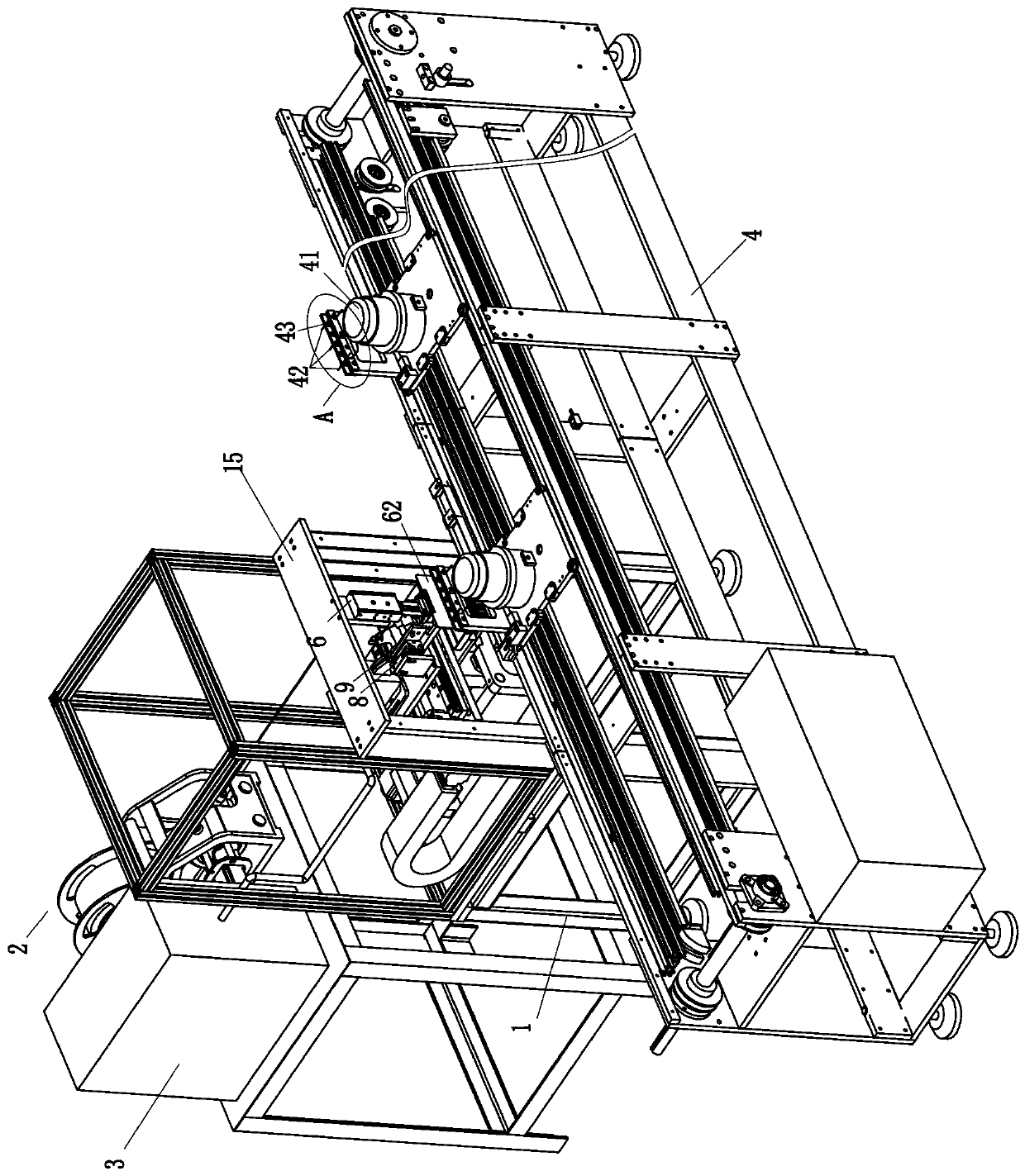
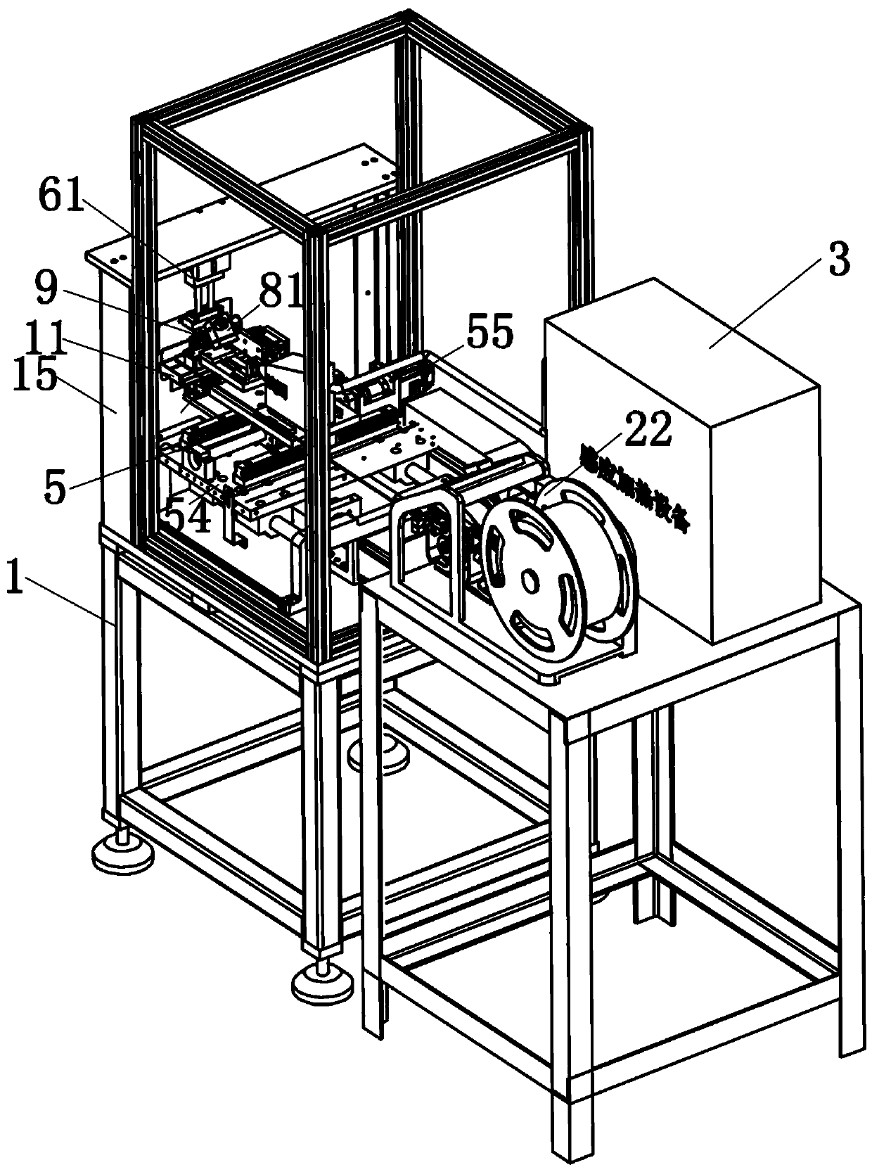
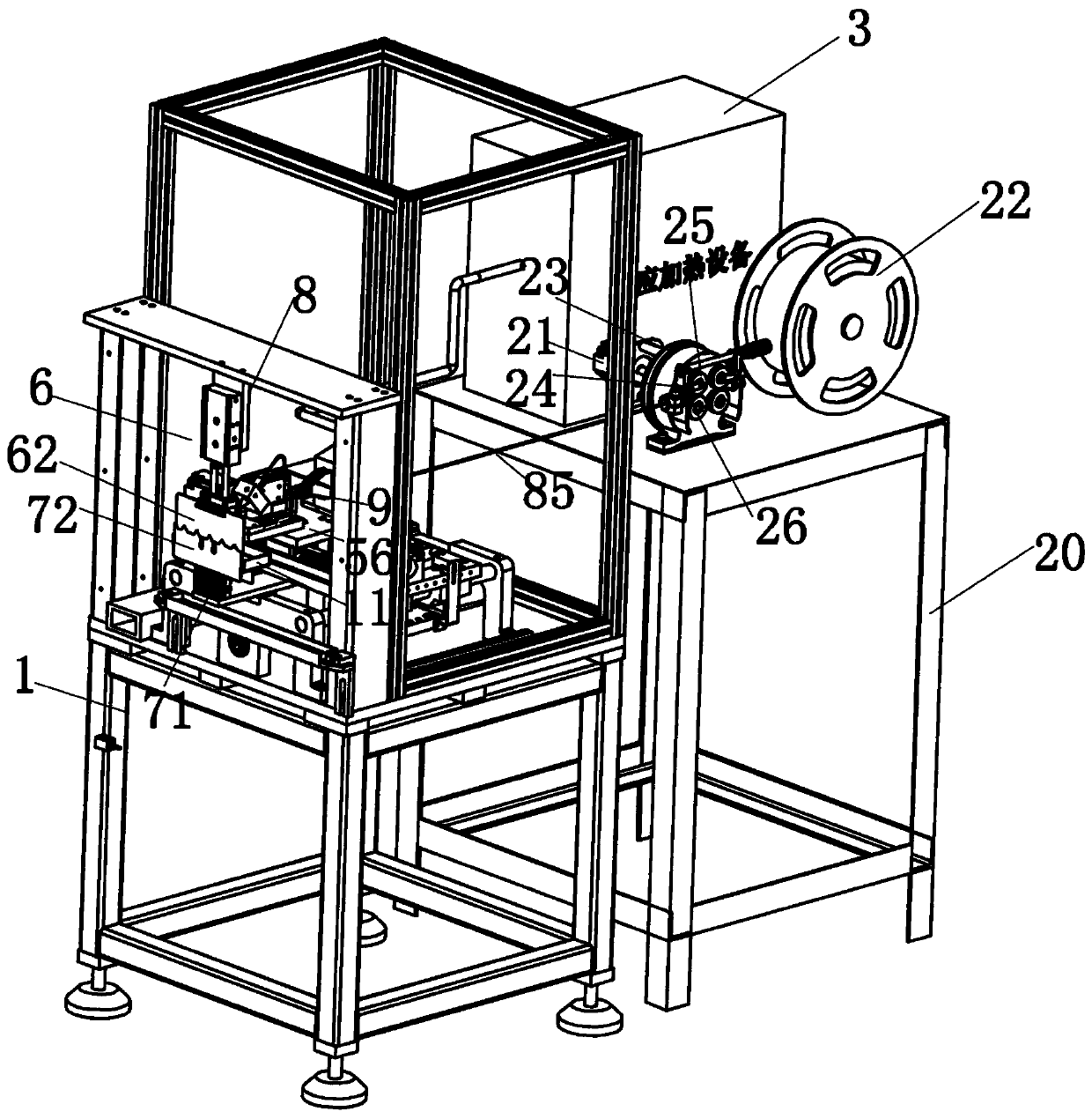
[0045] Embodiment one, such as Figure 1 to Figure 9 As shown, a high-frequency welding equipment for motor stator winding wiring includes: frame 1, ten-type sliding device 5, crimping head device 6, top wire device 7, wire feeder 2, wire output device 8, high-frequency welding and Forming device 9 , high frequency power generating device 3 and motor conveying line 4 .

[0046] The wire feeder 2 is located beside the frame 1 and is used to deliver the solder to the wire device 8 .

[0047] The high-frequency power generating device 3 is located beside the frame 1 and is used to provide high-frequency power to the high-frequency welding and forming device 9 .

[0048] The ten-shaped sliding device 5 is arranged on the frame 1, and is used to drive the wire output device 8 and the high-frequency welding and forming device 9 to slide back and forth, left and right.

[0049] The wire output device 8 is arranged on the ten-shaped sliding device 5 and is used to output solder to t...

Embodiment 2

[0076] Embodiment 2, the implementation of embodiment 2 is similar to that of embodiment 1, the only difference is that: the ten-shaped sliding device 5 includes a front and rear translation mechanism 51 and a left and right translation mechanism 52, and the left and right translation mechanism 52 includes Left and right translation motor 55 and left and right moving plate 56, described left and right moving plate 56 is arranged on the frame 1 along the horizontal sliding of frame 1 left and right directions, described left and right translation motor 55 is located on the frame 1 and with left and right moving plate 56 wires Rod transmission connection, the front and rear translation mechanism 51 includes a front and rear translation motor 53 and a front and rear moving plate 54, the front and rear moving plate 54 is horizontally slid on the left and right moving plates 56 along the front and rear direction of the frame 1, and the front and rear translation motor 53 is set On t...


PUM


Abstract

The invention relates to motor stator winding wiring high-frequency welding equipment. The equipment comprises a rack, a wire feeder for conveying solder to a wire outlet device, a cross-shaped sliding device used for driving the wire outlet device and a high-frequency welding and forming device to slide front, back, left and right, the wire outlet device used for outputting the solder to the high-frequency welding and forming device, and the high-frequency welding and forming device for welding the end of a first copper wire of a stator winding of a motor and the end of a second copper wire of a wiring terminal. By means of the cross-shaped sliding device, the wire feeder, the wire outlet device, the high-frequency welding and forming device, a high-frequency power generating device and the like, the procedures such as welding wire automatic conveying, aligning and feeding of the copper wires, high-frequency welding and forming are achieved, and then full-automatic welding and formingof a plurality of copper wires of the stator winding of the motor and a plurality of copper wires of the wiring terminal are achieved, so that the equipment is high in production efficiency, good inwelding effect, stable in welding quality and low in production cost.

Description

technical field [0001] The invention relates to the technical field of high-frequency welding equipment, in particular to a high-frequency welding equipment for motor stator winding wiring. Background technique [0002] At present, on the production line of compressors, the copper wires of multiple windings of the internal motor of the compressor need to be welded separately to the copper wires of the terminal in order to plug in and connect electricity. At present, on the production line of compressors, welding workers are generally , the copper wire of the terminal and the end of the copper wire of the winding are wound together), and then welded together with a high-temperature flame and solder. The welder generally burns the two into long strips so that the insulating sleeve can be easily set later. In this way, it is realized that the copper wires of each winding are welded with terminals. But the welding operation on the production line of the above-mentioned current ...

Claims


Application Information

Patent Timeline
IPC IPC(8): B23K13/00B23K37/04
CPCB23K13/00B23K37/0443B23K2101/32B23K2101/36
Inventor 桑达夫瞿晓鹏刘晖
Owner SANHE IND AUTOMATION EQUIP CO LTD SHUNDE DISTRICT FOSHAN CITY
Why Eureka
Try Eureka