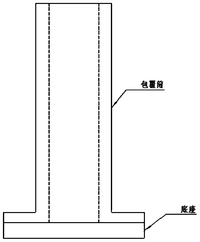
Coating die for side surface of medicine column of solid propellant and coating method
A solid propellant and coating technology, which is applied to household appliances, other household appliances, household components, etc., can solve problems such as long insertion time, lack of coating material, and poor vacuum degassing effect, so as to reduce coating man-hours , Improve coating efficiency and coating quality, and improve production efficiency
- Summary
- Abstract
- Description
- Claims
- Application Information
AI Technical Summary
Problems solved by technology
Method used
Image
Examples
Embodiment 1
[0060] After the mold base is put into the sealing ring, the base and the covering cylinder are tightly connected with screws, ready for use. Such as Image 6 As shown, the side coating of the grain column includes the following steps:
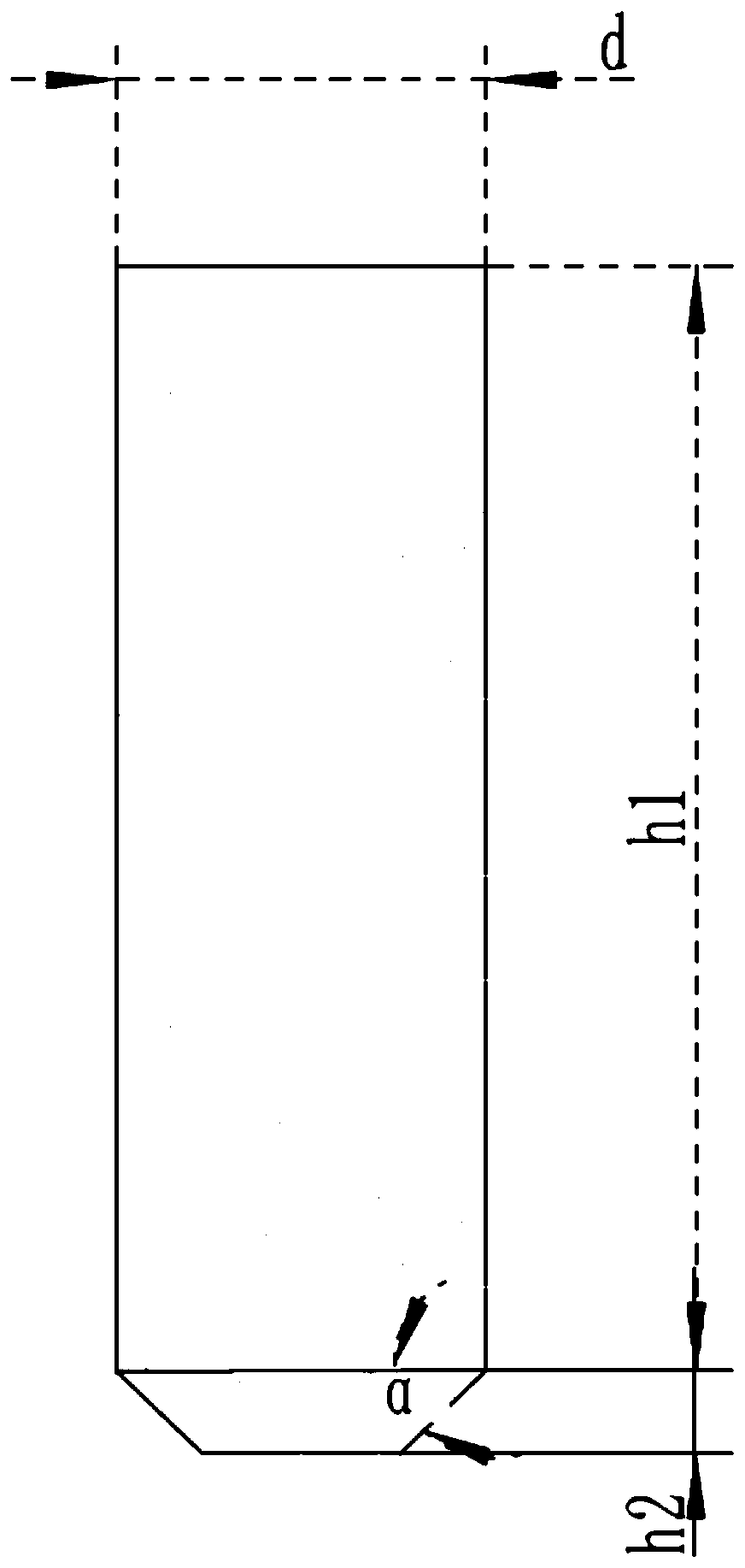
[0061] Step 1. Clean the surface of the grain column shaping. After shaping, the diameter d of the grain column to be coated is 35mm, the side surface needs to be covered with a height h1 of 100mm, the height of the trapezoidal boss h2 is 10mm, the bevel angle α is 45°, and the coating layer is average Thickness r is 0.7mm;
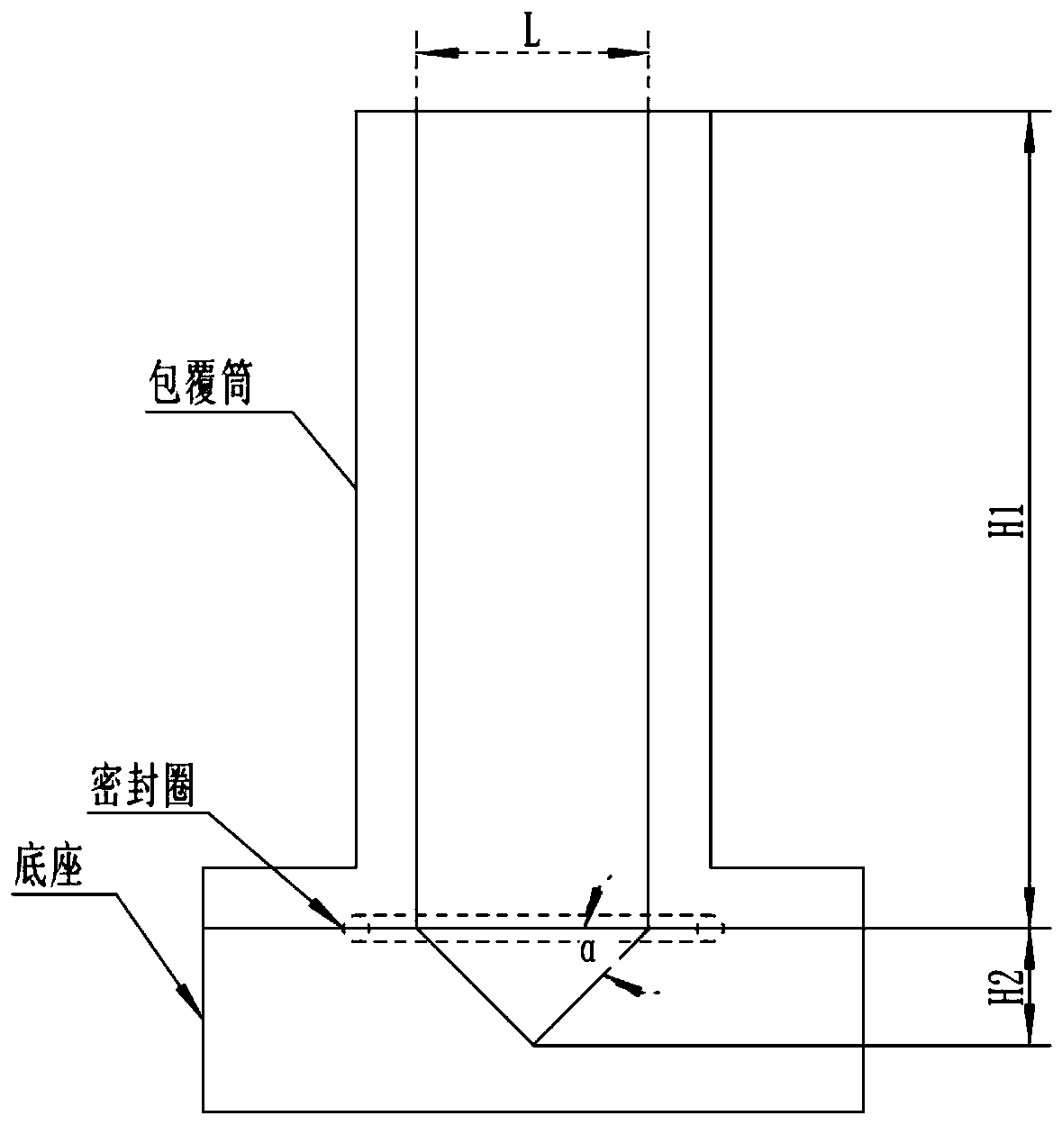
[0062] Step 2: Put the grain into the coating mold at room temperature (25°C ~ 35°C). The grain and the mold do not need to be preheated in advance. The inner diameter L of the mold coating cylinder for coating is 36.4mm, and the height is different Less than H1 is 150mm, the bevel angle α of the V-shaped groove of the base is 45°, the diameter L of the bottom surface of the V-shaped groove is 36.4mm, and the height H2 ...
Embodiment 2
[0071] According to the steps in Example 1, the diameter d of the grain to be coated is 60 mm, the side height h1 of the grain to be coated is 150 mm, the thickness r of the coating layer is 0.5 mm, and the oblique angle α of the trapezoidal boss of the grain after shaping is 30 °. The main dimensions of the mold used to coat the grain are: the height H1 of the coating cylinder is 250mm, and the inner diameter L is 61mm; the diameter L of the bottom surface of the V-shaped groove of the base is 61mm, and the bevel angle α is 30°. Preheat at 55℃~65℃.
[0072] The material of the coating layer is an epoxy coating layer. After the coating layer is prepared at room temperature, it is placed in an environment of 55°C to 65°C for preheating for 10min-15min. The viscosity of the slurry before adding the coating mold is measured to be 12Pa. s. The density of the cladding layer is approximately 1.0g / cm3. In theory, the mass required for the cladding layer to fill the gap between the ...
Embodiment 3
[0075] According to the steps of Example 1, the mold is put into a vacuum tank, and when the vacuum degree reaches -0.09MPa, keep it for 30 minutes; slowly deflate for 10 minutes, and take out the coated mold.
[0076] According to this condition, the grain was coated, and the defects of the coating layer on the side of the grain (lack of material, air bubbles, debonding) were inspected, and the bonding condition of the interface of the coated grain was ultrasonically tested. The results are shown in Table 1.
PUM
| Property | Measurement | Unit |
|---|---|---|
| Bevel | aaaaa | aaaaa |
| Height | aaaaa | aaaaa |
| Viscosity | aaaaa | aaaaa |
Abstract
Description
Claims
Application Information
 - R&D
- Intellectual Property
- Life Sciences
- Materials
- Tech Scout
- Unparalleled Data Quality
- Higher Quality Content
- 60% Fewer Hallucinations
Browse by: Latest US Patents, China's latest patents, Technical Efficacy Thesaurus, Application Domain, Technology Topic, Popular Technical Reports.
© 2025 PatSnap. All rights reserved.Legal|Privacy policy|Modern Slavery Act Transparency Statement|Sitemap|About US| Contact US: help@patsnap.com


