Novel multifunctional road-maintenance construction vehicle

A multi-functional technology for road maintenance, applied to mechanically driven excavators/dredgers, earth movers/shovels, construction, etc., can solve problems such as drainage ditch blockage, sewage cleaning treatment, and affecting drainage efficiency, etc., to achieve Reduced workload, high degree of automation, and smooth suction process

Inactive Publication Date: 2019-12-24
张占成
View PDF5 Cites 0 Cited by
  • Summary
  • Abstract
  • Description
  • Claims
  • Application Information

AI Technical Summary

Problems solved by technology

[0002] There are often some small stones, silt, and fallen dead leaves in the roadside drainage ditch on both sides of some provincial roads and township roads. If these debris are not cleaned up in time, the drainage ditch will be blocked, which will affect The drainage performance of the drainage ditch affects the drainage efficiency in the rainy season or when the water flow is large. At present, sewage suction vehicles are used to clean up the sundries and silt accumulated in the drainage ditch to ensure the smooth flow of the drainage ditch. ;
[0003] However, at present, there are many branch roads along the main roads such as some township roads or provincial roads, which are used to lead to various cities or villages. At this time, some of the drainage ditches arranged on both sides of the main road will be under the branch roads and

Method used


Image

  • Novel multifunctional road-maintenance construction vehicle
  • Novel multifunctional road-maintenance construction vehicle
  • Novel multifunctional road-maintenance construction vehicle

Examples


Embodiment 1

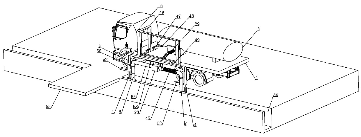
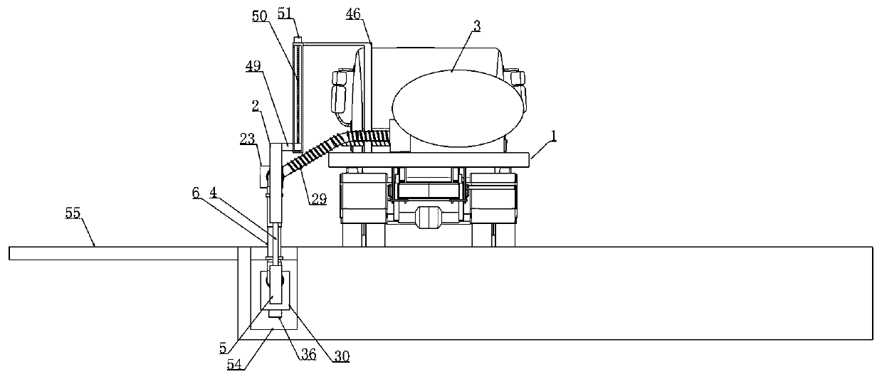
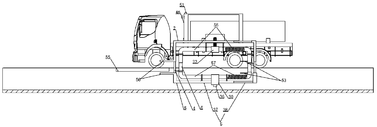
[0042] Embodiment 1, a new type of multifunctional road maintenance construction vehicle, includes a sewage suction vehicle 1 and a sewage suction device 3 is provided on the sewage suction vehicle 1, and it is characterized in that the sewage suction is fixedly provided with a longitudinal distance adjustment device And the first U-shaped frame 2 is vertically slidably connected to the longitudinal distance adjusting device, and the first U-shaped frame 2 is driven by the driving device arranged on the longitudinal distance adjusting device, and the first U-shaped frame 2 is fixed with the first U-shaped frame 2. A U-shaped pipe 56 and the middle part of the first U-shaped pipe 56 is integrally connected with a first valve control device, the first valve control device communicates with the sewage suction device 3, and the two cantilever arms of the first U-shaped frame 2 are vertically slid and connected with telescopic The rod 4 and the telescopic rod 4 are driven by the adj...

Embodiment 2

[0050]Embodiment 2, on the basis of Embodiment 1, the first U-shaped frame 2 is provided with a first sliding cavity 7 in the two cantilever arms, and the second U-shaped frame 5 is provided with a second sliding cavity 8 in the two cantilever arms, and the telescopic rod 4 is up and down. The two ends are respectively slidably connected in the first sliding chamber 7 and the second sliding chamber 8, and the adjustment device includes an active rod 9 which is rotatably installed in the first sliding chamber 7, and the active rod 9 is arranged with a rotating shaft at intervals from the center of the shaft. The externally threaded cylinder 10 in the first slide chamber 7 is threadedly fitted between the externally threaded cylinder 10 and the telescopic rod 4, and the outer wall of the active rod 9 is fixed with a first drive plate 11 along its diameter direction. Two second drive plates 12 are fixed at intervals along its diameter direction on the 10 inner walls and the first ...

Embodiment 3

[0052] Embodiment 3, on the basis of Embodiment 2, the transmission device includes a transmission rod 14 that is axially slidably connected with the active rod 9, and the bottom of the telescopic rod 4 is provided with a locking cavity 15, and the transmission rod 14 is rotatably mounted on the locking chamber. In the cavity 15, the bottom of the transmission rod 14 is connected with the positioning device and drives the positioning device.

[0053] When this embodiment is in use, refer to the attached Figure 10 As shown, the bottom of the active rod 9 is axially slidably connected with a transmission rod 14 and the transmission rod 14 is rotatably installed in the locking cavity 15, as attached Figure 9 As shown, the bottom of the transmission rod 14 is connected with the positioning device and drives the positioning device under the drive of the active rod 9, and finally releases the positioning of the positioning device to the telescopic rod 4, and the transmission rod 1...


PUM


Abstract

The invention relates to a novel multifunctional road-maintenance construction vehicle. By adoption of the novel multifunctional road-maintenance construction vehicle, the problems that an existing drainage ditch trash-removal vehicle cannot carry out trash removal continuously and smoothly when a drainage ditch is blocked by a branched road is effectively solved. According to the technical schemeadopted to solve the problem, when the novel multifunctional road-maintenance construction vehicle carries out trash removal long a trunk road, a trash suction pipe network can be switched to realizeuninterrupted trash suction in the case of a branched road, namely, a trash suction device enables the head end of the trash suction pipe network communicating with the trash suction device to open so as to make the head end of the trash suction pipe network pass over the branched road; when the trash suction pipe network passes over the branched road, the head end is controlled by a detection device to close, at this moment, the detection device controls the tail end of the trash suction pipe network to open to make the tail of the trash suction pipe network pass over the branched road, andthe trash suction pipe network sequentially passes over the branched road section by section without stopping the trash suction vehicle, so that the whole trash suction process is smooth, the automation degree is high, the workload of maintainers is greatly reduced, and the trash removal efficiency is improved.

Description

technical field [0001] The invention relates to the field of road construction, in particular to a novel multifunctional road maintenance construction vehicle. Background technique [0002] There are often some small stones, silt, and fallen dead leaves in the roadside drainage ditch on both sides of some provincial roads and township roads. If these debris are not cleaned up in time, the drainage ditch will be blocked, which will affect The drainage performance of the drainage ditch affects the drainage efficiency in the rainy season or when the water flow is large. At present, sewage suction vehicles are used to clean up the sundries and silt accumulated in the drainage ditch to ensure the smooth flow of the drainage ditch. ; [0003] However, at present, there are many branch roads along the main roads such as some township roads or provincial roads, which are used to lead to various cities or villages. At this time, some of the drainage ditches arranged on both sides of...

Claims


Application Information

Patent Timeline
IPC IPC(8): E02F3/88E02F3/90E02F5/28
CPCE02F3/88E02F3/8816E02F3/90E02F5/28
Inventor 张占成冀文灿赵燕王海飞刘如意刘萌谢卫东王佩张春香
Owner 张占成
Why Eureka
Try Eureka