
Quantum imaging system for quantum radar

A quantum imaging and quantum radar technology, applied in radio wave measurement systems, transmission systems, digital transmission systems, etc., can solve the problems of low imaging efficiency, reduced system stability, slow speed, etc., to improve imaging efficiency and secure bit errors. Rate limit, the effect of preventing forgery and tampering

Pending Publication Date: 2019-12-27
赵义博 +1
View PDF0 Cites 2 Cited by
  • Summary
  • Abstract
  • Description
  • Claims
  • Application Information

AI Technical Summary

Problems solved by technology

The traditional quantum imaging technology needs to divide the light source into two beams and detect the coincidence count between the two beams, the imaging efficiency is low and the speed is slow
Polarization encoding, however, means that the polarization state of photons transmitted in space will be affected by atmospheric disturbances, and will change significantly when scattered on the surface of the target object, which greatly reduces the stability of the system.

Method used


Image

  • Quantum imaging system for quantum radar
  • Quantum imaging system for quantum radar
  • Quantum imaging system for quantum radar

Examples


specific Embodiment approach

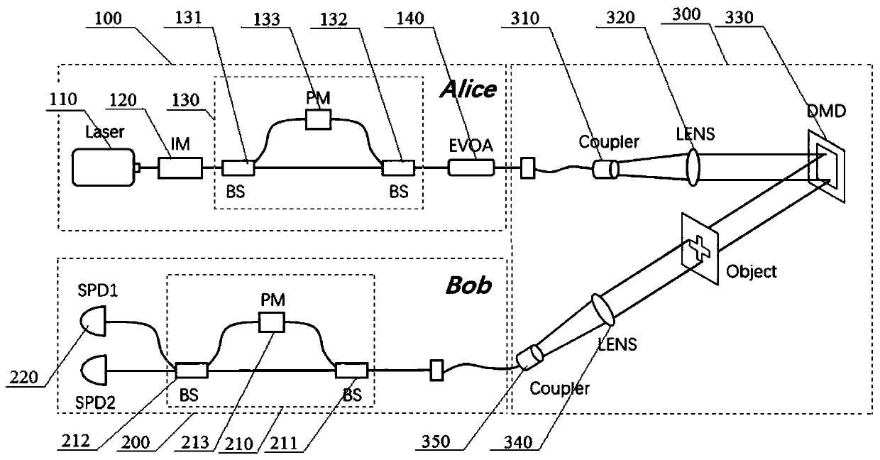
[0030] The present invention adopts the computing ghost imaging technology based on digital micromirror (hereinafter referred to as: DMD) and decoy state BB84 phase coding QKD technology, and specific implementation is as follows:

[0031] (1) Computational imaging process

[0032] Modulating DMD can preset the light intensity distribution emitted by the sending end to I i (x, y)(1≤i≤M), M is the number of modulations of the DMD, and through the synchronization of the DMD and the single photon detector at the receiving end, the corresponding photon count B can be obtained every time the DMD is modulated i (1≤i≤M), finally the image expression of the target object can be obtained

[0033]

[0034] in, is the average value of photon counts.

[0035] (2) Estimation of the lower bound of bit error rate

[0036] The sending end prepares signal states, decoy states, and vacuum state pulses with an average photon number of μ, ν, and 0. After being detected by the imaging syst...


PUM


Abstract

The invention provides a quantum imaging system for a quantum radar. The quantum imaging system comprises a transmitting end, a receiving end and a quantum imaging unit; the transmitting unit comprises a pulse laser, an intensity modulator, a phase encoder and an adjustable attenuator which are orderly connected with each other; the receiving end comprises a phase decoder and two single photon detector which are respectively connected with the phase decoder; and the quantum imaging unit comprises a first optical fiber coupler, a projecting lens, a digital micro-mirror device, a collecting lensand a second optical fiber coupler. Compared with the prior art, the system of the invention adopts a decoy state of light pulses to carry out an imaging process, so that the anti-interference capability can be effectively improved, and target object imaging is prevented from being falsified and tampered; the system adopts a phase coding scheme, and has higher stability than a polarization codingscheme; and meanwhile, the imaging efficiency is improved, and the imaging time is shortened, so that a safer bit error rate threshold is obtained, and the anti-interference capability is effectivelyimproved.

Description

technical field [0001] The invention relates to the technical field of quantum polarization encoding, in particular to a quantum imaging system for quantum radar. Background technique [0002] With the development of quantum information technology, it has become the trend of today's technology to use the principle of quantum mechanics to solve the security problems existing in the classical application field. For example, in the military field, the application of quantum imaging technology to radar detection, the so-called quantum radar, greatly improves the detection concealment and resolution, and has extremely high application value. When applying quantum imaging technology to the radar field, it may still face potential threats of jamming and spoofing. This is because when the existing radar faces a target with active jamming capability, its detection signal will be intercepted by the target object or a third party and at the same time transmit a jamming signal with the...

Claims


Application Information

Patent Timeline
IPC IPC(8): G01S17/89G01S7/481G01S7/487H04L9/08
CPCG01S7/4818G01S7/487G01S17/89H04L9/0852
Inventor 王东张万里赵义博宋萧天
Owner 赵义博
Learn More