Polishing equipment and method

A technology of equipment and grinding tools, which is applied in the direction of grinding/polishing equipment, metal processing equipment, grinding machines, etc., can solve the problem of low grinding efficiency and achieve the effect of improving grinding efficiency

Inactive Publication Date: 2019-12-31
CRRC QINGDAO SIFANG CO LTD
View PDF8 Cites 14 Cited by
  • Summary
  • Abstract
  • Description
  • Claims
  • Application Information

AI Technical Summary

Problems solved by technology

[0005] Embodiments of the present invention provide a grinding device and a grinding method, at least solving the technical problem of low grinding efficiency caused by manual grinding of objects in the prior art

Method used


Image

  • Polishing equipment and method
  • Polishing equipment and method
  • Polishing equipment and method

Examples


Embodiment 1

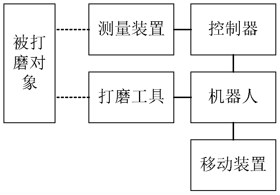
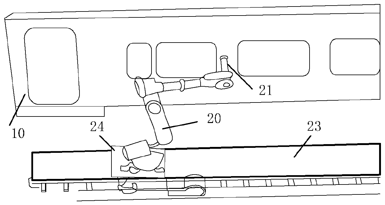
[0035] According to an embodiment of the present invention, an embodiment of a grinding device is provided. It should be noted that the grinding device provided in this embodiment can be applied in the grinding of high-speed rail car bodies, and can also be applied in other fields that require equipment grinding. in, figure 1 is a schematic diagram of a polishing device according to an embodiment of the present invention, such as figure 1 As shown, the grinding equipment includes: a measuring device, a robot and a controller.

[0036] Among them, the measuring device is used to collect the data of the polished object.

[0037] Optionally, the measurement device may be an optical measurement system, wherein the optical measurement system may include at least one of the following: an optical detector, an X-ray detector, a laser side thickness meter, a gloss detector, a light transmittance tester, a color difference Instruments, infrared scanners, thermometers, etc.

[0038] I...

Embodiment 2

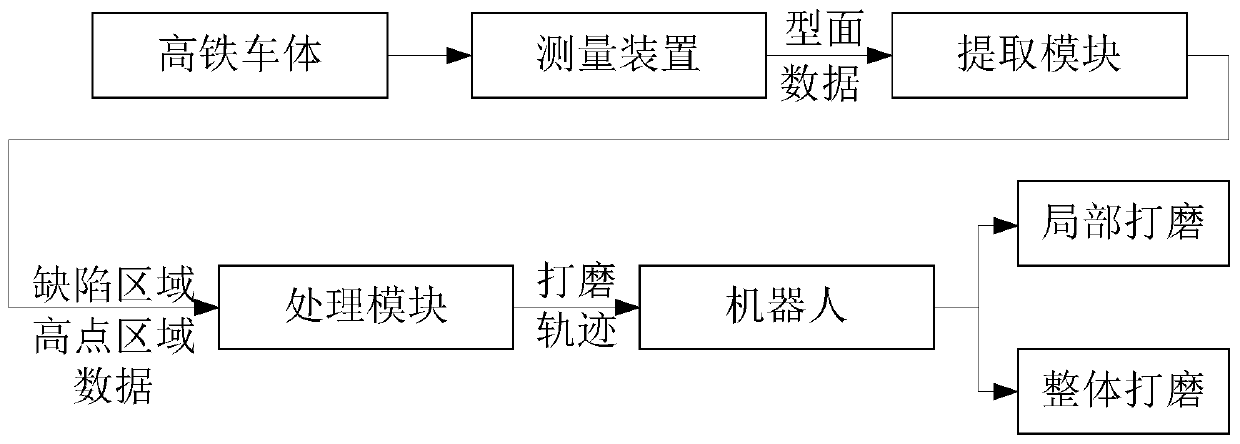
[0062] According to an embodiment of the present invention, an embodiment of a grinding method is also provided. It should be noted that the controller in Embodiment 1 can be used as the execution subject of this embodiment. In addition, the steps shown in the flow diagrams of the figures may be performed in a computer system, such as a set of computer-executable instructions, and, although a logical order is shown in the flow diagrams, in some cases, the sequence may be different. The steps shown or described are performed in the order herein.

[0063] Figure 7 is a flow chart of a grinding method according to an embodiment of the present invention, as Figure 7 As shown, the method includes the following steps:

[0064] Step S702, receiving the collected data of the polished object.

[0065] In this embodiment, the object to be polished can be a high-speed rail car body, and the data of the object to be polished is the data collected by various instruments in the optical...

Embodiment 3

[0089] According to another aspect of the embodiments of the present invention, a processor is also provided, and the processor is used to run a program, wherein the polishing method in the above-mentioned embodiment 2 is executed when the program is running.


PUM


Abstract

The invention discloses polishing equipment and method. The polishing equipment comprises a measuring device, a robot and a controller. The measuring device is used for collecting data of a polished object. The robot is mounted on a movable device, a polishing tool is mounted at one end of the robot. The controller is in communication with the measuring device and the robot and is used for analyzing the received data to obtain high spot area data, and the robot is controlled to execute the action of high spot polishing based on the high spot area data. According to the polishing equipment andmethod, the technical problem that due to the fact that in the prior art, a manual operation mode is adopted for polishing the polished object, the polishing efficiency is low is solved.

Description

technical field [0001] The invention relates to the technical field of industrial processing, in particular to a grinding device and a grinding method. Background technique [0002] In the production process of the high-speed rail car body, in order to ensure the smoothness and beauty of the car body surface, it is necessary to carry out multiple putty scraping and putty grinding operations on the car body surface. However, due to the fluidity of the scraping putty and the instability of the force during the manual scraping process, the putty coating after scraping is prone to defects such as fibroids, step edges, continuous bumps, bosses, and pits. Therefore, During the putty grinding process, the raised curve area needs to be smoothed. [0003] At present, the putty grinding process of the high-speed rail car body is mainly done by manual operation, which has problems such as poor working environment, low production efficiency, high labor intensity, and poor consistency o...

Claims


Application Information

Patent Timeline
IPC IPC(8): B24B27/00B24B27/033B24B49/12B24B49/14B24B51/00B25J9/16B25J11/00
CPCB24B27/0007B24B27/0084B24B27/033B24B49/12B24B49/14B24B51/00B25J9/1602B25J9/1664B25J9/1679B25J11/0065
Inventor 夏海渤张志毅王浩孙禹李丽
Owner CRRC QINGDAO SIFANG CO LTD
Why Eureka
Try Eureka