A dust removal device for large circular knitting machine
A technology of dust removal device and large circular knitting machine, which is applied in the direction of textiles, papermaking, knitting, etc., can solve the problems of unreasonable dust removal, achieve reasonable dust removal effect, wide application range, and prevent secondary dust pollution.
- Summary
- Abstract
- Description
- Claims
- Application Information
AI Technical Summary
Problems solved by technology
Method used
Image
Examples
Embodiment 1
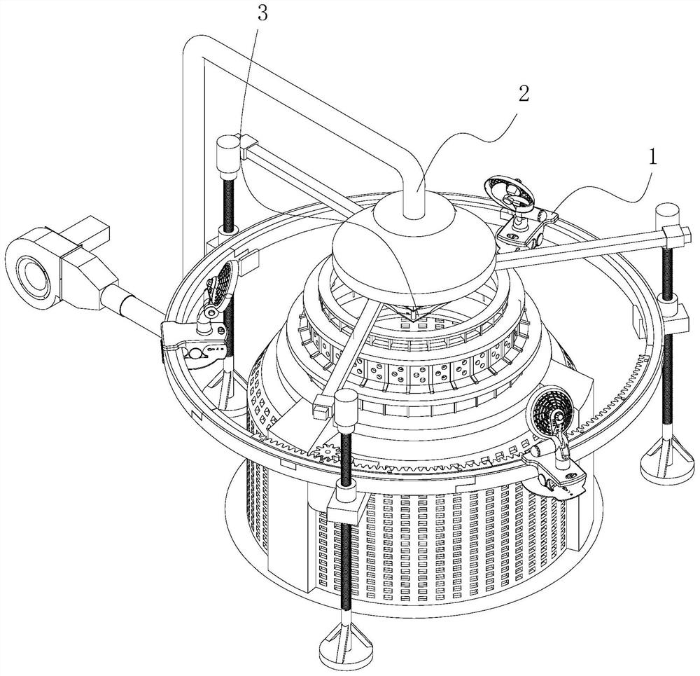
[0043] Embodiment one, a kind of dust removal device for large circular knitting machine, such as figure 1 As shown, the blowing and dust removal assembly 1 is arranged around the axis of the large circular knitting machine to blow and dust the transmission device and yarn of the large circular knitting machine. Collect and filter together the draft dust collection assembly 2 and the anti-fall assembly 3 that is arranged directly below the draft dust collection assembly 2 to prevent part of the dust from falling directly into the large circular knitting machine due to the turbulence of the air flow.
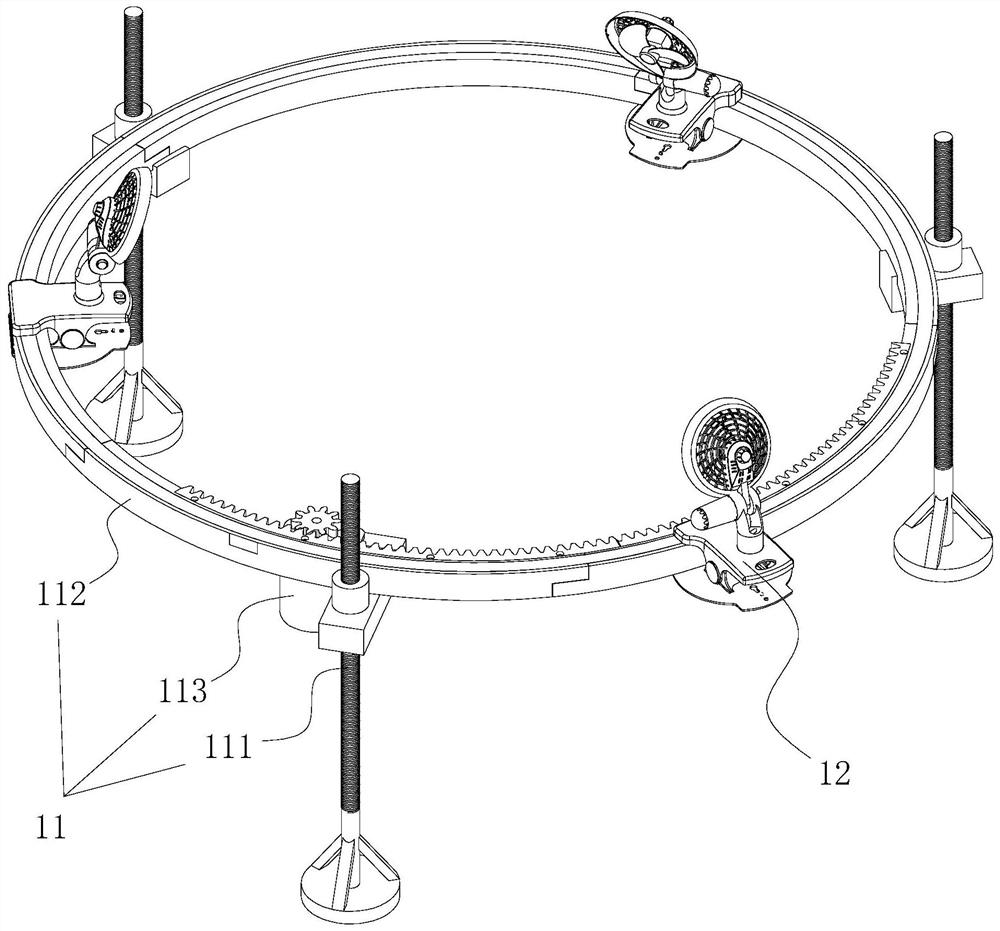
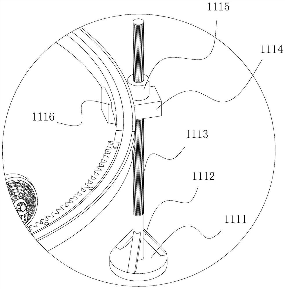
[0044] combine figure 1 with figure 2 As shown, the blowing and dust removal assembly 1 includes a support frame 11 arranged on the outer wall of the large circular knitting machine frame and arranged circumferentially around the axis of the large circular knitting machine frame, and installed on the support frame 11 for the transmission device and yarn of the large circular kn...
Embodiment 2
[0054] Embodiment two: if Figure 10 As shown, the difference from Embodiment 1 is that the blowing device 12 of Embodiment 2 includes a ring-shaped blower that communicates with the outlet pipe 233 disposed on the water tank 231 through a hose and is installed on the ring-shaped support 112 . Blowing pipe 124, several roads are provided with the blowing hose 125 that communicates with blowing pipe 124 inside and along the length direction equidistant arrangement of blowing pipe 124 and the sleeve pipe 126 that several outer walls are connected with ring support 112 rotation, each The blowing hoses 125 pass through the sleeves 126 respectively, and each blowing hoses 125 are arranged towards the axis of the ring support 112; An accommodating groove 1122 is arranged around the axis of the ring-shaped support member 112 , and the blowing pipe 124 is installed in the accommodating groove 1122 and fixed in the accommodating groove 1122 by means of an arc-shaped connecting plate. ...
PUM
 Abstract
Description
Claims
Application Information
 - R&D
- Intellectual Property
- Life Sciences
- Materials
- Tech Scout
- Unparalleled Data Quality
- Higher Quality Content
- 60% Fewer Hallucinations
Browse by: Latest US Patents, China's latest patents, Technical Efficacy Thesaurus, Application Domain, Technology Topic, Popular Technical Reports.
© 2025 PatSnap. All rights reserved.Legal|Privacy policy|Modern Slavery Act Transparency Statement|Sitemap|About US| Contact US: help@patsnap.com


