Drying equipment
A technology of drying equipment and cadres, which is applied in the field of clothes dryers, can solve the problems of long drying time and difficulty in use, and achieve the effects of improving energy efficiency, occupying less space, and compact structure
- Summary
- Abstract
- Description
- Claims
- Application Information
AI Technical Summary
Problems solved by technology
Method used
Image

Examples
Embodiment 1
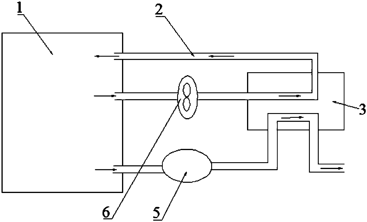
[0040] This embodiment introduces a drying equipment, including a drying part, a drying air duct 2, a first heat exchanger 3 and a compressor 5. The outlet of the drying air duct 2 is connected to the drying part, and the first heat exchange The device 3 includes a first flow channel and a second flow channel through which the internal working fluid can exchange heat. The working fluid in the drying air channel 2 flows through the first flow channel, and the working fluid discharged from the compressor 5 flows through the second flow channel to compress The machine 5 is set inside the drying air duct 2.
[0041] In the present invention, by arranging the compressor 5 inside the drying air duct 2, the heat dissipated during the operation of the compressor 5 is dissipated to the inside of the drying air duct 2, and the compressor 5 is also used as an auxiliary heater in the drying air duct 2. But the existence, thereby speeding up the heating speed of the drying system, and improvi...
Embodiment 2
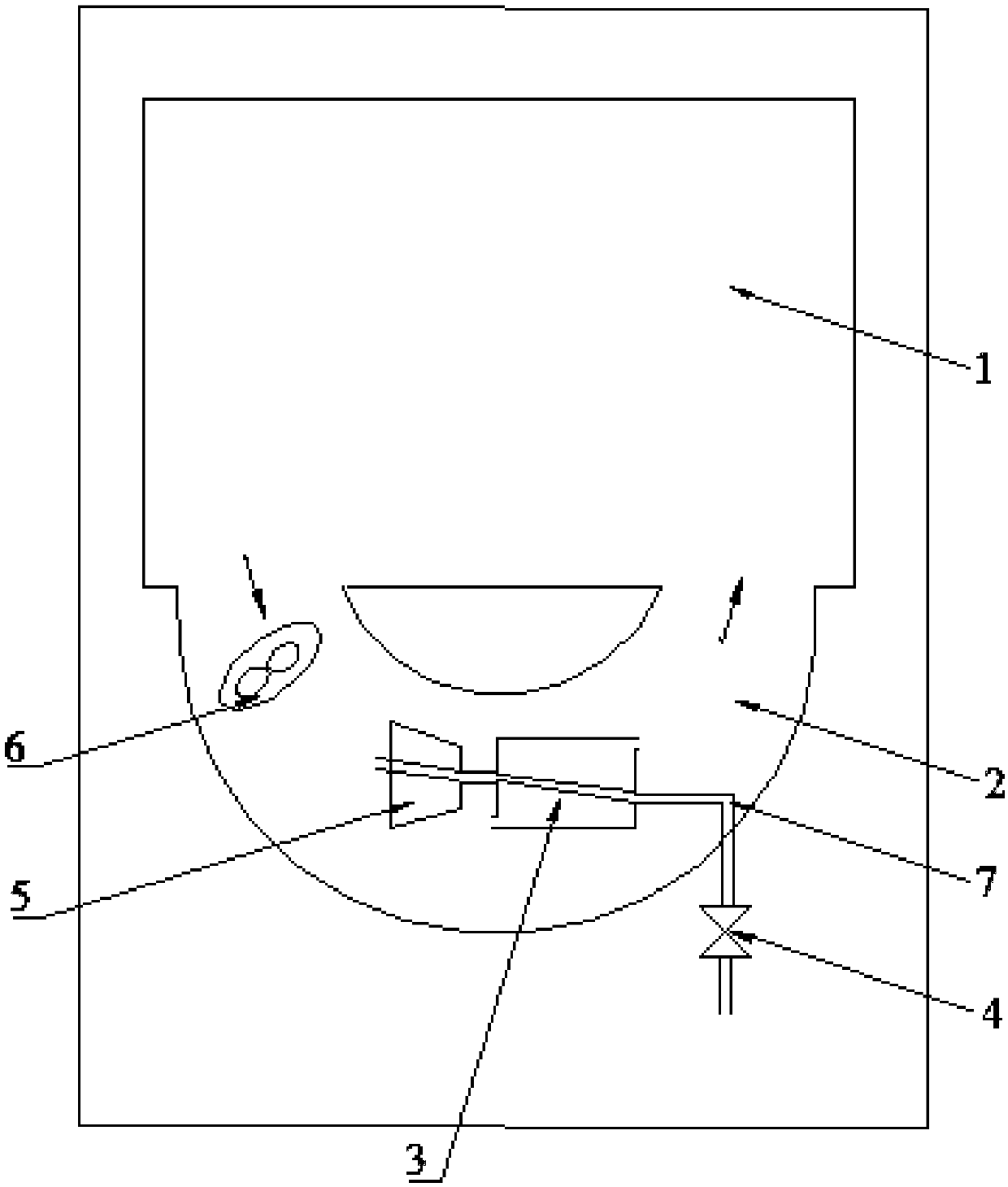
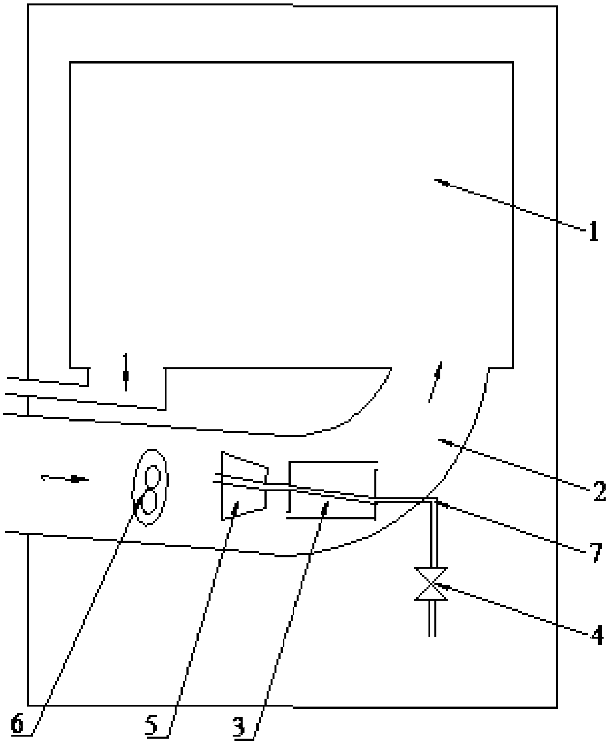
[0048] Such as Figure 2-4 As shown, the difference between this embodiment and the first embodiment is that the inlet of the drying air duct 2 is connected to the drying drum 1, so that a circulation path is formed between the drying air duct 2 and the drying drum 1; preferably, the drying air The inlet of the channel 2 is connected with the outer space of the dryer, and the drying cylinder 1 is connected with the outer space of the dryer via an exhaust pipe.
[0049] The inlet of the compressor 5 is connected to the drying cylinder 1, and the discharge pipe 7 of the compressor 5 is connected to the discharge pipe of the dryer; preferably, the discharge pipe 7 of the compressor 5 passes through the throttling device 4 and / or gas-liquid separation The device is connected with the discharge pipe of the dryer; when the discharge pipe 7 of the compressor 5 is connected with the discharge pipe of the dryer through the throttle device 4 and the gas-liquid separation device, the thrott...
Embodiment 3
[0054] Such as figure 2 As shown, the difference between this embodiment and the first and second embodiments is that there is a gap between the outer wall of the compressor 5 and the inner wall of the drying air duct 2 for the passage of working fluid.
[0055] The present invention realizes the circulation of working fluid by providing a gap between the outer wall of the compressor 5 and the inner wall of the drying air duct 2.
[0056] Preferably, there are gaps between the compressor 5 and the inner wall of the drying air duct 2 on the outer periphery thereof. In order to achieve the above structure, the compressor 5 can be fixed inside the drying air duct 2 through a bracket.
[0057] With the above arrangement, the operating compressor 5 fully exchanges heat with the vapor flowing to the compressor 5, thereby further improving the energy efficiency of the drying system.
PUM
 Abstract
Description
Claims
Application Information
 - R&D
- Intellectual Property
- Life Sciences
- Materials
- Tech Scout
- Unparalleled Data Quality
- Higher Quality Content
- 60% Fewer Hallucinations
Browse by: Latest US Patents, China's latest patents, Technical Efficacy Thesaurus, Application Domain, Technology Topic, Popular Technical Reports.
© 2025 PatSnap. All rights reserved.Legal|Privacy policy|Modern Slavery Act Transparency Statement|Sitemap|About US| Contact US: help@patsnap.com