
Input shaping residual vibration suppression method and system adapting to trajectory errors of motion system

An input shaping and motion system technology, applied in general control systems, control/regulation systems, program control, etc., can solve problems such as increasing the waiting time between processes, reducing production efficiency and accuracy, and reducing the system's response speed to commands.

Active Publication Date: 2019-12-31
SHENZHEN COLIBRI TECH
View PDF7 Cites 11 Cited by
  • Summary
  • Abstract
  • Description
  • Claims
  • Application Information

AI Technical Summary

Problems solved by technology

[0004] The purpose of the present invention is to provide an input shaping residual vibration suppression method that adapts to the trajectory error of the motion system. It aims to solve the problem that the vibration of the mechanical structure will not only reduce the response speed of the system to instructions, but also increase the waiting time between processes and reduce production efficiency. problems with precision

Method used


Image

  • Input shaping residual vibration suppression method and system adapting to trajectory errors of motion system
  • Input shaping residual vibration suppression method and system adapting to trajectory errors of motion system
  • Input shaping residual vibration suppression method and system adapting to trajectory errors of motion system

Examples


Embodiment Construction

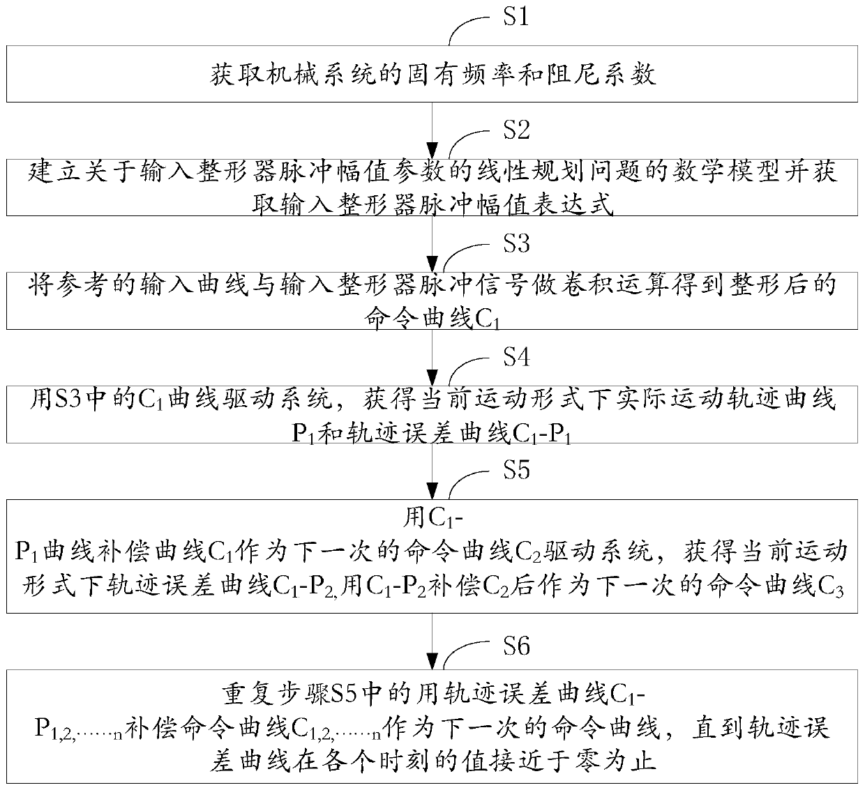
[0075] Such as figure 1 As shown, the input shaping residual vibration suppression method adapted to the trajectory error of the motion system provided by the present invention is described in detail as follows:

[0076] Step S1, get the natural frequency w of the mechanical system 0 and damping coefficient ε; obtain the natural frequency w in the mechanical system respectively 0 and damping coefficient ε.

[0077] Step S2, establishing a mathematical model of the linear programming problem about the input shaper pulse amplitude parameter and obtaining the input shaper pulse amplitude expression; establishing a mathematical model about the linear programming problem of the input shaper pulse amplitude parameter, using the impulse response The expression of the pulse amplitude of the input shaper is solved by the method; the mathematical model of the linear programming problem about the pulse amplitude parameter of the input shaper is established, and the Laplace transform is...


PUM


Abstract

The invention provides an input shaping residual vibration suppression method adapting to trajectory errors of a motion system, comprising the following steps: S1, acquiring the inherent frequency anddamping coefficient of a mechanical system; S2, establishing a mathematical model about a linear programming problem of pulse amplitude parameters of an input shaper, and acquiring a pulse amplitudeexpression of the input shaper; S3, performing convolution operation on an input signal for reference and a pulse signal of the input shaper to obtain a shaped command curve C1; S4, using the C1 curvein the S3 to drive the system to obtain an actual motion trajectory curve P1 and a trajectory error curve C1-P1 under the current motion form; S5, using the C1-P1 curve to compensate the curve C1 toobtain a next command curve C2, using the curve C2 to drive the system to obtain a trajectory error curve C1-P2 under the current motion form, and using C1-P2 to compensate C2 to obtain a next commandcurve P3; and S6, repeating S5 to use the trajectory error curves C1-P1, 2,...n to compensate the command curves P1, 2,...n to obtain a next command curve until the value of the trajectory error curve at each moment is close to zero. According to the method for suppressing residual vibration through the input shaper, other hardware equipment does not need to be added, and cost is saved.

Description

technical field [0001] The invention belongs to the field of mechanical control technology improvement, and in particular relates to an input shaping residual vibration suppression method and system adapting to a motion system track error. Background technique [0002] Motor-driven mechanical motion structures including industrial robots, CNC machine tools, and CNC mechanical structures have requirements for high speed, high precision, and high stability. Due to the existence of transmission components such as reducers or pulleys, mechanical motion structures usually have a certain degree of flexibility. During low-speed operation and start and stop stages, the end of the mechanical movement structure will vibrate. The vibration of the mechanical structure will not only reduce the response speed of the system to commands, but also increase the waiting time between processes, reducing production efficiency and precision. Therefore, effective measures must be taken to suppre...

Claims


Application Information

Patent Timeline
IPC IPC(8): G05B19/19
CPCG05B19/19G05B2219/35349
Inventor 张晓波夏飞扬何彩英
Owner SHENZHEN COLIBRI TECH
Learn More