External rotor flywheel pulse synchronous generator system

A pulse synchronous, permanent magnet synchronous motor technology, applied in the direction of electromechanical devices, electrical components, electric components, etc., can solve the problems of long shafting, low system power density and reliability, etc., and achieve short shafting, light weight, The effect of high rotor strength

Active Publication Date: 2021-05-04
HARBIN INST OF TECH
View PDF6 Cites 0 Cited by
  • Summary
  • Abstract
  • Description
  • Claims
  • Application Information

AI Technical Summary

Problems solved by technology

[0006] The purpose of the present invention is to solve the problems of long shafting of the entire unit and low power density and reliability of the system in the existing flywheel pulse generator set. The present invention provides an outer rotor flywheel pulse synchronous generator system

Method used


Image

  • External rotor flywheel pulse synchronous generator system
  • External rotor flywheel pulse synchronous generator system
  • External rotor flywheel pulse synchronous generator system

Examples


Embodiment 1

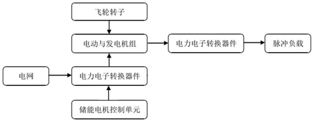
[0056] Embodiment 1: as Figure 2 to Figure 5 As shown, the outer rotor flywheel pulse synchronous generator system of this embodiment includes an input inverter, an input motor, an outer rotor permanent magnet synchronous motor, an output rectifier, an excitation current adjustment unit and an inertial flywheel;

[0057] The output end of the input inverter is connected to the lead-out line of the input motor, the rotor of the input motor is coaxially connected to the rotor of the outer rotor permanent magnet synchronous motor, the output end of the armature winding of the outer rotor permanent magnet synchronous motor is connected to the AC input end of the output rectifier connection; the output end of the armature winding of the outer rotor permanent magnet synchronous motor is connected to the excitation current adjustment unit; the rotor of the outer rotor permanent magnet synchronous motor is coaxially connected with the inertial flywheel.

[0058] The outer rotor flywh...

Embodiment 2

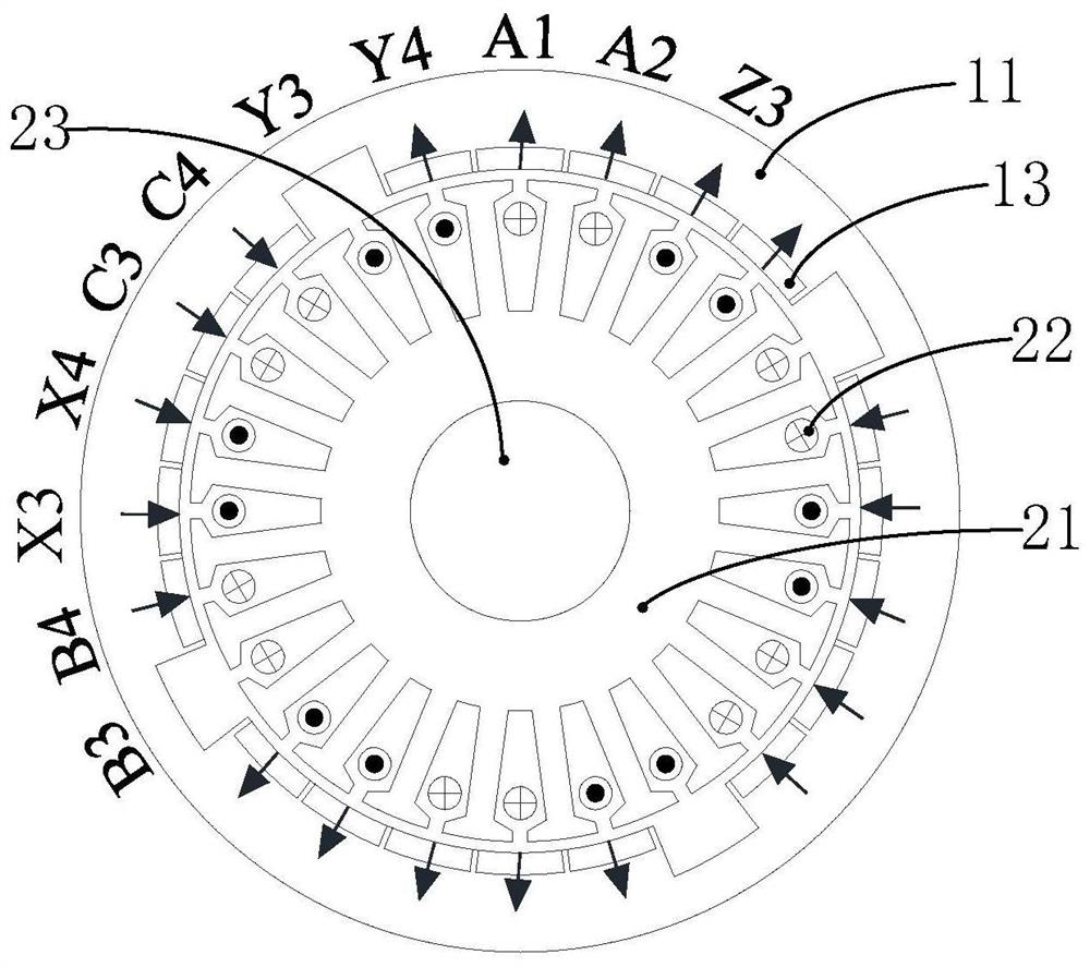
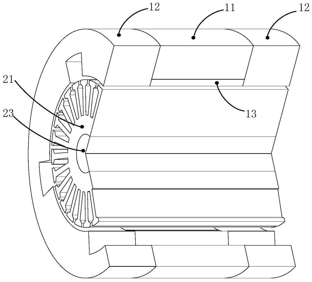
[0077] Embodiment 2: as Figure 2-6 As shown, the outer rotor flywheel pulse synchronous generator system of this embodiment includes an input inverter, an outer rotor permanent magnet synchronous motor, an output rectifier, an excitation current adjustment unit and an inertial flywheel; there are three sets of outer rotor permanent magnet synchronous motor stators Multi-phase armature windings, one of which is the input power winding, such as Image 6 As shown, two sets of output power windings, the output end of the input inverter is connected to the lead-out wire of the input power winding of the outer rotor permanent magnet synchronous motor rotor, the phase difference between the two sets of output power windings is 30 degrees electrical angle, each set The output ends of the output power windings are connected to an excitation current adjustment unit, and the lead-out wires of each set of output power windings are connected to the AC input end of an output rectifier, and...


PUM


Abstract

In order to solve the problems of long shafting of the entire unit and low power density and reliability of the system in the existing flywheel pulse generator set, the present invention provides an external rotor flywheel pulse synchronous generator system, which belongs to the technical field of motors and power electronics. The invention includes an input inverter, an input motor, an outer rotor permanent magnet synchronous motor, an output rectifier and an excitation current adjustment unit; The rotor of the synchronous motor is connected coaxially, the output end of the armature winding of the outer rotor permanent magnet synchronous motor is connected to the AC input end of the output rectifier; the output end of the armature winding of the outer rotor permanent magnet synchronous motor is connected to the excitation current adjustment unit; the motor is an anti-salient pole structure, when the motor speed drops, the output voltage adjustment of the system can be realized by controlling the output reactive current of the excitation current adjustment unit, the control is easy, and the excitation power is small.

Description

technical field [0001] The invention relates to an external rotor flywheel pulse synchronous generator system, which belongs to the technical field of motors and power electronics. Background technique [0002] The flywheel pulse generator is a flywheel energy storage device that uses the large inertia of the shaft system to store energy, and coaxial motor / generator to realize electromechanical energy conversion. There are two types of flywheel energy storage devices currently in use or under development: the first type is that the power levels of energy storage and energy release are equivalent, and one motor can be used to alternately realize the functions of electric power generation and power generation. The small and medium-capacity magnetic levitation flywheel energy storage system is for this The first type has the characteristics of compact structure and high efficiency, and is generally used as a flywheel battery; the second type is that the energy storage power is ...

Claims


Application Information

Patent Timeline
Patent Type & Authority Patents(China)
IPC IPC(8): H02K1/27H02K1/16
CPCH02K1/165H02K1/2786H02K2201/03
Inventor 寇宝泉张浩泉赵元胜张艳清
Owner HARBIN INST OF TECH
Why Eureka
Try Eureka