Numerical control machine tool water cooling and scrap discharging system

A CNC machine tool and water-cooling technology, which is applied to metal processing machinery parts, maintenance and safety accessories, metal processing equipment, etc., can solve the problems of secondary damage of chips, inability to complete chip cooling, and inability to discharge chips in time, so as to prevent Small chips damage the machine tool, real-time efficient operation, reliable principle effect

Pending Publication Date: 2020-01-03
青岛欧普特精工机床有限公司
View PDF2 Cites 0 Cited by
  • Summary
  • Abstract
  • Description
  • Claims
  • Application Information

AI Technical Summary

Problems solved by technology

At present, general machine tools only provide a chip removal machine outside the machine tool to collect chips, which cannot solve the secondary damage that may be caused by high temperature chips in time, and can only rely on natural cooling; Discharge according to the set path, which has a negative impact on the life of the machine tool
The existing chip collection schemes are either inefficient or high-temperature dangerous, and they do not completely solve the problem of chip cooling and collection; the two technical solutions disclosed in Chinese patents 201721383563.9 are both chip removal devices for CNC machine tools, and their functions are both The discharged chips are collected through the conveyor belt outside the machine tool, and the cooling of the chips cannot be completed; therefore, it is necessary to design a water-cooled chip removal system for CNC machine tools, which has good social and economic benefits.

Method used


Image

  • Numerical control machine tool water cooling and scrap discharging system
  • Numerical control machine tool water cooling and scrap discharging system
  • Numerical control machine tool water cooling and scrap discharging system

Examples


Embodiment 1

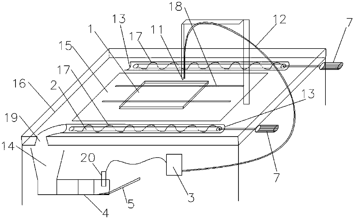
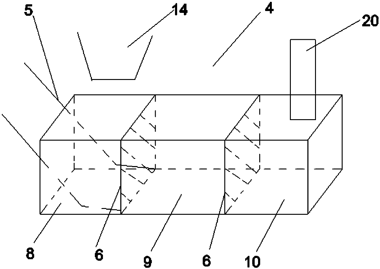
[0012] The main configuration of the CNC machine tool water-cooled chip removal system involved in this embodiment includes a workbench 1, a chip removal dragon 2, a cooler 3, a water tank 4, a conveyor belt 5, a filter screen 6, a keel motor 7, a cooling box 8, a filter box 9, Circulation box 10, faucet 11, cold water pipe 12, chip removal groove 13, material inlet 14, chip removal table 15, machine tool chassis 16, advancing thread 17, guide rail 18, chip removal port 19, pumping motor 20; chip removal table 15 is laid flat on the upper center of the machine tool chassis 15, and the center line of the top surface of the chip removal table 15 has an inclined slope downward to the left and right bottom edges. slide into the chip removal groove 13; a workbench 1 is arranged above the chip removal table 15, and the workbench 1 with a cuboid steel structure is slidingly connected with the chip removal table 15; There are two semi-cylindrical chip removal grooves 13, and a chip re...

Embodiment 2

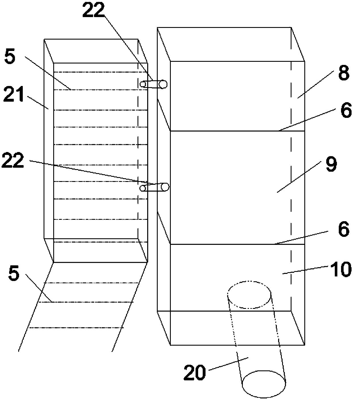
[0016] The main configuration of the CNC machine tool water-cooled chip removal system involved in this embodiment includes a workbench 1, a chip removal dragon 2, a cooler 3, a water tank 4, a conveyor belt 5, a filter screen 6, a keel motor 7, a cooling box 8, a filter box 9, Circulation box 10, faucet 11, cold water pipe 12, chip removal groove 13, collection box 21, chip removal table 15, machine tool chassis 16, advancing thread 17, guide rail 18, chip removal port 19, pumping motor 20; chip removal table 15 Tiling is set in the center of the upper part of the machine tool chassis 15, and the center of the top surface of the chip removal table 15 has an inclined slope to the left and right bottom edges, with a slope of 1-30°, so that the chips slide to the sides of the chip removal table 15 and enter the chip removal In the groove 13; above the chip removal table 15, a workbench 1 is arranged, and the workbench 1 of cuboid steel structure is slidingly connected with the ch...


PUM


Abstract

The invention belongs to the technical field of manufacturing of large numerical control machine tool cooling equipment, and relates to a numerical control machine tool cooling and scrap discharging device, in particular to a numerical control machine tool water cooling and scrap discharging system. The system simultaneously realizes cooling, discharging and collecting of scraps through water circulation, and comprises a workbench, scrap discharging augers, a cooling machine, a water tank, a conveying plate, filter screens, a keel motor, a cooling box, a filter box, a circulating box, a faucet, a cold water pipe, scrap discharging grooves, a feed inlet, a scrap discharging table, a machine tool bottom frame, a propelling thread, a guide rail, a scrap discharging port and a water pumping motor. The cold water pipe makes the faucet connected with water cooled two times in parallel, the faucet and the scraps can be better cooled in time, and safety is ensured. By means of a scrap discharging path from the scrap discharging table to the scrap discharging grooves to the scrap discharging augers, the situation that fine scraps damage a machine tool is completely prevented, and the highest collection efficiency is ensured. Real-time and efficient operation is achieved through water circulation. The system is reasonable in structure, reliable in principle and environmentally friendly in application.

Description

Technical field: [0001] The invention belongs to the technical field of large-scale numerical control machine tool cooling equipment manufacturing, and relates to a numerical control machine tool cooling chip removal device, in particular to a numerical control machine tool water-cooled chip removal system, which simultaneously realizes cooling, discharge and collection of chips through water circulation. Background technique: [0002] CNC machine tools will produce chips of different shapes during the cutting process of metal or non-metal materials. According to the formation state of chips, chips can be divided into different shapes such as rolls, lumps, strips, blocks and granules. Because the chips are cut by the faucet and have a relatively high temperature, it is necessary to cool the chips; at the same time, the chips need to be discharged and collected in time to prevent damage to the entire machine tool equipment and failure. At present, general machine tools only ...

Claims


Application Information

Patent Timeline
Patent Type & Authority Applications(China)
IPC IPC(8): B23Q11/00
CPCB23Q11/0067
Inventor 张荣
Owner 青岛欧普特精工机床有限公司
Why Eureka
Try Eureka