Clothes-hanger shaped spinning die head runner structure for uniform melt distribution
A spinning die, uniform distribution technology, applied in melt spinning, spinneret assemblies, textiles and papermaking, etc., can solve the problems of loss, uniform distribution, large die height, etc., and achieve processing and installation positioning accuracy The effect of reducing requirements, improving work efficiency, and saving manufacturing costs
- Summary
- Abstract
- Description
- Claims
- Application Information
AI Technical Summary
Problems solved by technology
Method used
Image
Examples
Embodiment 1
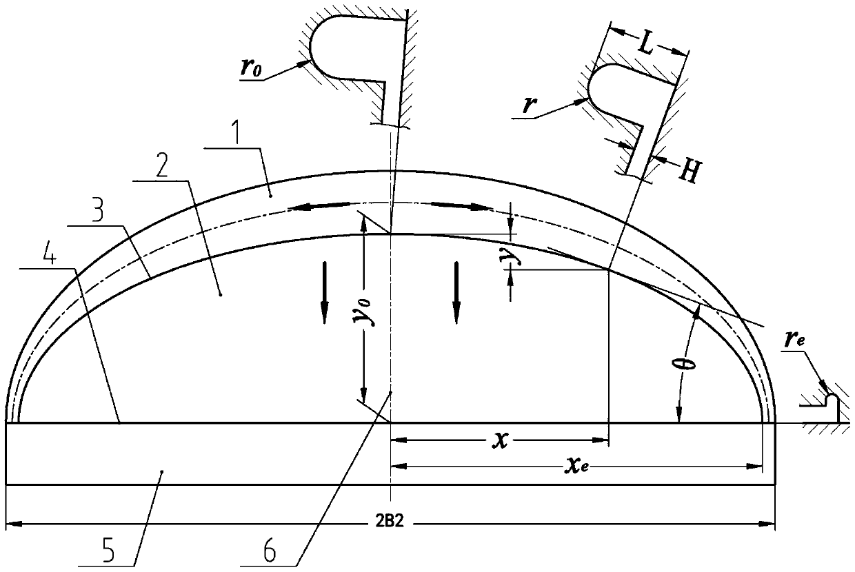
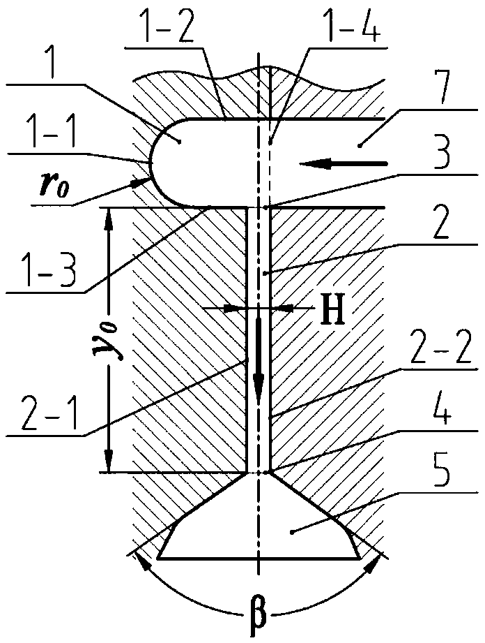
[0133] Such as figure 1 with 2 As shown, a clothes hanger-shaped spinning die runner structure for evenly distributing the melt,
[0134] The die flow channel structure includes a manifold 1 and a slit channel 2; the manifold 1 is arranged on the upper part of the slit channel 2;
[0135]Wherein, the manifold 1 is in the shape of a clothes hanger; the manifold 1 is a horizontal U-shaped structure, and the horizontal U-shaped structure includes a bottom end 1-1, a first side wall 1-2 of the manifold, a second manifold Two side walls 1-3 and the third side wall 1-4 of the manifold, the bottom end 1-1 of the horizontal U-shaped structure is a semicircular structure with a radius r, and the first side wall 1-2 of the manifold One end is connected tangentially to one side of the bottom end 1-1 of the horizontal U-shaped structure, and the other end of the first side wall 1-2 of the manifold is vertically connected to the third side wall 1-4 of the manifold , one end of the secon...
Embodiment 2
[0153] Such as figure 1 with figure 2 As shown, the present embodiment provides a clothes-hanger-shaped spinning die, which includes the runner structure of the clothes-hanger-shaped spinning die in Embodiment 1; the clothes-hanger-shaped spinning die also includes a feed pipe, and the feed The pipe communicates with the feed port on the third side wall 1-4 of the manifold of the horizontal U-shaped structure; the feed pipe is used to connect external equipment and transport the melt into the manifold 1; the hanger-shaped The spinning die head also includes a balance cavity 5 which communicates with the outlet 4 of the slit channel.
[0154] In a preferred embodiment of the present invention, the shape of the balance chamber 5 is not particularly limited, it can be a cavity with a specific volume, the upper end of the balance chamber communicates with the outlet of the slit flow channel, and the balance chamber The lower end can communicate with other spinning components; t...
Embodiment 3
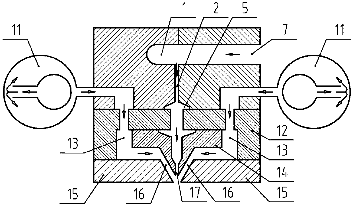
[0158] A meltblown device, such as image 3 As shown, the melt-blown device includes the hanger-shaped spinning die described in Embodiment 2, and the melt-blown device also includes a spinning assembly, an air knife 15 and a device 11 for evenly distributing fluid; the spinning The assembly includes a distribution plate 12 and a spinneret 14; the spinneret 14 forms a spinneret hole 17 for melt ejection; the spinneret 14, the distribution plate 12 and an air knife 15 form a draft hot air flow channel 13 , for the circulation of the hot air flow; the air knife 15 and the spinneret 14 form an air gap slit 16 for accelerating the hot air flow and ejecting it;
[0159] The balance cavity 5 at the bottom of the hanger-shaped spinning die communicates with the spinneret hole 17 formed by the spinneret 14 in the spinning assembly, and the outlet end of the device 11 for evenly distributing the fluid is connected to the distribution plate in the spinning assembly 12. One end of the d...
PUM
| Property | Measurement | Unit |
|---|---|---|
| width | aaaaa | aaaaa |
| diameter | aaaaa | aaaaa |
| radius | aaaaa | aaaaa |
Abstract
Description
Claims
Application Information
 - R&D
- Intellectual Property
- Life Sciences
- Materials
- Tech Scout
- Unparalleled Data Quality
- Higher Quality Content
- 60% Fewer Hallucinations
Browse by: Latest US Patents, China's latest patents, Technical Efficacy Thesaurus, Application Domain, Technology Topic, Popular Technical Reports.
© 2025 PatSnap. All rights reserved.Legal|Privacy policy|Modern Slavery Act Transparency Statement|Sitemap|About US| Contact US: help@patsnap.com


