Ultra-thin optical amplification module and application thereof

An optical magnification, ultra-thin technology, applied in the optical field, can solve the problems of affecting the experience effect, reducing light energy, dark imaging, etc., to achieve the effect of reducing space volume, improving comfort, and shortening length

Inactive Publication Date: 2020-01-03
平行现实(杭州)科技有限公司
View PDF3 Cites 6 Cited by
  • Summary
  • Abstract
  • Description
  • Claims
  • Application Information

AI Technical Summary

Problems solved by technology

In order to ensure the magnification effect, multiple lenses are needed, so the entire optical magnification module is still large in size; at th

Method used


Image

  • Ultra-thin optical amplification module and application thereof
  • Ultra-thin optical amplification module and application thereof
  • Ultra-thin optical amplification module and application thereof

Examples


Embodiment Construction

[0024] The purpose and effects of the present invention will become clearer by describing the present invention in detail according to the accompanying drawings and preferred embodiments. It should be understood that the specific embodiments described here are only used to explain the present invention, not to limit the present invention.

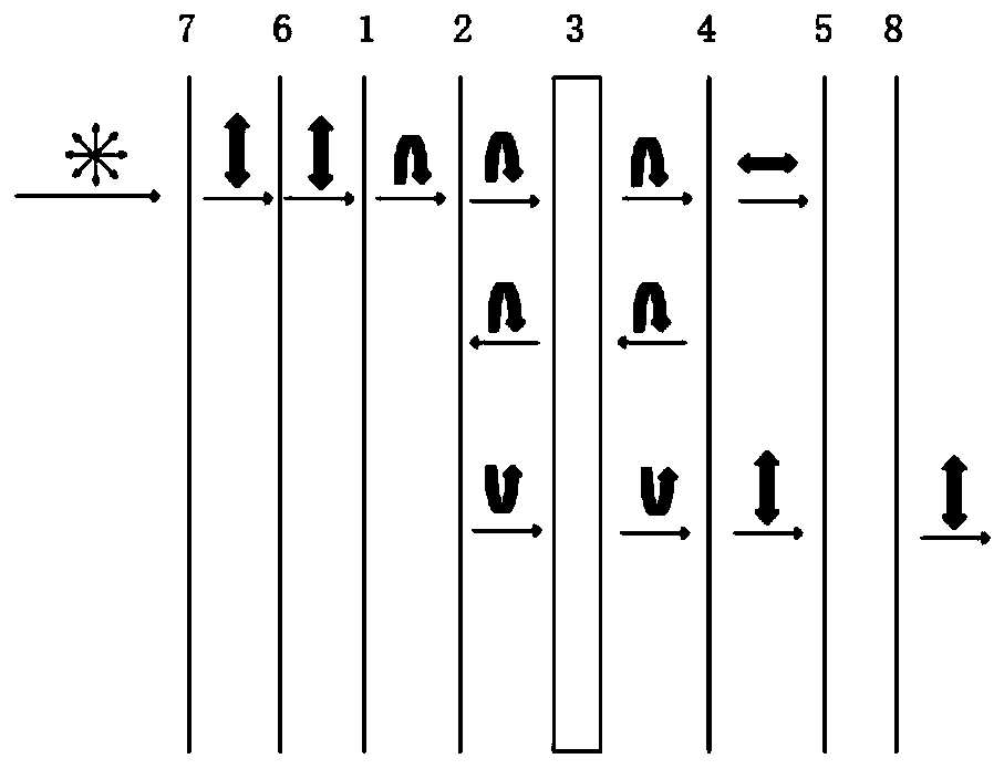
[0025] Such as figure 1 As shown, the ultra-thin optical magnification module of the present invention includes a first phase retarder 1, a partially transmissive and partially reflective light-transmitting element 2, a lens or lens group 3, and a second phase retarder arranged sequentially from the object side to the image side. Sheet 4 , first reflective polarizer 5 . The reflectance of the partially transmissive and partially reflective light-transmitting element 2 is 10%-90%. It is assumed here that the light emitted by the light source is the first linearly polarized light, which is converted into circularly polarized light by the fi...


PUM


Abstract

The invention discloses an ultra-thin optical amplification module. The ultra-thin optical amplification module comprises a first phase delay chip, a light transmitting element for partially transmitting and partially reflecting, a lens or lens group, a second phase delay chip, and a first reflection-type polaroid, which are sequentially arranged from an object side to an image side, and the reflectivity of the light transmitting element for partially transmitting and partially reflecting is 10% to 90%; and the lens or lens group is a spherical lens, an aspherical lens, a free-form surface lens, a liquid crystal lens, a super lens, or the like. The ultra-thin optical amplification module disclosed by the invention adopts a polarized light path and the light transmitting element for partially transmitting and partially reflecting to increase an effective optical path in a short distance and shorten the length in an optical axis direction of the optical module, thereby greatly reducing the volume of an optical system comprising the optical amplification module.

Description

technical field [0001] The invention belongs to the field of optics, and in particular relates to an ultra-thin optical amplification module and its application. Background technique [0002] Currently existing optical amplification modules usually use a combination of multiple optical elements to obtain better magnification and imaging effects, but this often increases the size and volume of the optical amplification module. Most of the existing VR display devices on the market, including VR smart glasses, smart helmets and various head-mounted display devices, etc., mostly obtain the required magnification by increasing the distance between the display screen and the lens or the thickness of the lens. These methods will undoubtedly increase the volume of the optical amplification system, and the weight of the whole machine will also increase accordingly, which directly affects the user's experience and reduces the user's experience effect. [0003] In order to provide a b...

Claims


Application Information

Patent Timeline
IPC IPC(8): G02B27/28G02B27/01
CPCG02B27/0172G02B27/28G02B2027/0178
Inventor 鲍鹏飞
Owner 平行现实(杭州)科技有限公司
Why Eureka
Try Eureka