Supercharge Your Innovation With Domain-Expert AI Agents!

Micro-bubble hydrogenation reactor and application thereof

A hydrogenation reactor and hydrogenation reaction technology, applied in chemical instruments and methods, hydrocarbon oil cracking, petroleum industry, etc., can solve the problem of blockage of microporous metal-containing precipitates on the tube, insufficient gas-liquid reaction space, and gas-liquid mixing Small chamber volume and other issues, to avoid local overheating and deactivation, high industrial application value, and promote the effect of gas-liquid mass transfer

Pending Publication Date: 2020-01-07
INST OF PROCESS ENG CHINESE ACAD OF SCI
View PDF6 Cites 5 Cited by
  • Summary
  • Abstract
  • Description
  • Claims
  • Application Information

AI Technical Summary

Problems solved by technology

[0006] CN103143302A discloses a continuous microbubble reactor, in which a plurality of transversely arranged horizontal microporous tubes and vertically distributed vertical microporous tubes are arranged in a plurality of reaction chambers, although this design method is beneficial to realize the uniform distribution of gas and improve the reaction efficiency, but the reactor design is too complex and the production cost is high
In addition, the microbubble reactor in this invention is mostly used to treat metal-containing wastewater, but most of the microporous tubes are installed near the slag discharge port, which makes the micropores on the tubes easily blocked by metal-containing sediments
[0007] CN208066329U discloses a novel microbubble type gas-liquid reactor that utilizes an annular air chamber to uniformly feed in the axial direction, but the annular air chamber occupies more reactor interior space, resulting in gas-liquid mixing at the center of the reactor. The volume of the cavity is too small, which makes the gas-liquid reaction space insufficient, which is not conducive to expanding the scale of the reaction

Method used


Image

  • Micro-bubble hydrogenation reactor and application thereof
  • Micro-bubble hydrogenation reactor and application thereof
  • Micro-bubble hydrogenation reactor and application thereof

Examples


Embodiment 1

[0120] This embodiment provides a kind of upflow type micro-bubble hydrogenation reactor, such as Figure 4 As shown, the reactor includes a reactor main body and a membrane tube microbubble generating device 5;

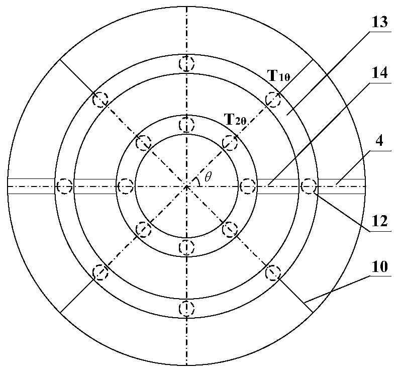
[0121] The reactor body includes a cylindrical reactor shell 2 with an inner diameter of 280mm arranged on the outermost side of the reactor. The inside of the reactor shell 2 is sequentially provided with a gas-liquid distributor 3, a gas injection pipe 4, Catalyst bed 6 and metal screen 7, the gas injection pipe 4 is located on both sides of the lower part of the catalyst bed 6, a feed inlet 1 is provided directly below the reactor shell 2, and a feed port 1 is provided directly above the reactor shell 2 There is an exhaust port 8, and a discharge port 9 is provided on the upper side; the reactor shell 2 is made of plexiglass, and the catalyst bed 6 includes catalyst particles required for hydrogenation reaction, and the gas-liquid distribution The device 3 is a s...

Embodiment 2

[0129] This embodiment provides an upflow micro-bubble hydrogenation reactor, which includes a reactor body and a membrane tube micro-bubble generating device 5;

[0130] The reactor body includes a cylindrical reactor shell 2 with an inner diameter of 280mm arranged on the outermost side of the reactor. The inside of the reactor shell 2 is sequentially provided with a gas-liquid distributor 3, a gas injection pipe 4, Catalyst bed 6 and metal screen 7, the gas injection pipe 4 is located on both sides of the lower part of the catalyst bed 6, a feed inlet 1 is provided directly below the reactor shell 2, and a feed port 1 is provided directly above the reactor shell 2 There is an exhaust port 8, and a discharge port 9 is provided on the upper side; the reactor shell 2 is made of plexiglass, and the catalyst bed 6 includes catalyst particles required for hydrogenation reaction, and the gas-liquid distribution The device 3 is a sieve plate distributor, the aperture of the sieve h...

Embodiment 3

[0135] This embodiment provides an upflow micro-bubble hydrogenation reactor, which includes a reactor body and a membrane tube micro-bubble generating device 5;

[0136] The reactor body includes a cylindrical reactor shell 2 with an inner diameter of 400 mm arranged on the outermost side of the reactor. The inside of the reactor shell 2 is sequentially provided with a gas-liquid distributor 3, a gas injection pipe 4, Catalyst bed 6 and metal screen 7, the gas injection pipe 4 is located on both sides of the lower part of the catalyst bed 6, a feed inlet 1 is provided directly below the reactor shell 2, and a feed port 1 is provided directly above the reactor shell 2 There is an exhaust port 8, and a discharge port 9 is provided on the upper side; the reactor shell 2 is made of plexiglass, and the catalyst bed 6 includes catalyst particles required for hydrogenation reaction, and the gas-liquid distribution The device 3 is a sieve plate distributor, the aperture of the sieve ...


PUM

PropertyMeasurementUnit
Fill heightaaaaaaaaaa
The average particle sizeaaaaaaaaaa
Diameteraaaaaaaaaa

Abstract

The invention relates to a micro-bubble hydrogenation reactor and application thereof. According to the reactor, a membrane tube micro-bubble generating device is arranged in a catalyst bed layer; a gas can be input into the catalyst bed layer in the form of microbubbles, the problem that in the prior art, the microbubbles are distributed unevenly in the axial direction is solved, gas-liquid mixing is enhanced, liquid backmixing is reduced, and meanwhile a membrane tube microbubble generating device is simple in structure and easy to machine, assemble and disassemble. The reactor is used in ahydrogenation reaction, the hydrogenation reaction rate can be controlled by introducing different types of gases into an injection pipe of the reactor, the controllability of the hydrogenation reaction is enhanced, overheating, coking or inactivation of the catalyst can be avoided, the reaction efficiency is improved, the service life of the catalyst is prolonged, and the reactor has high industrial application value.

Description

technical field [0001] The invention relates to the technical field of petrochemical equipment, in particular to a micro-bubble hydrogenation reactor and its application. Background technique [0002] Hydrogenation reactors are often used in the petroleum refining industry to convert difficult-to-use heavy residues into light oils through hydrocracking reactions. In the actual residual oil hydrogenation industry, local overheating of the bed, coking of the catalyst, and severe back-mixing often occur, mainly due to the uneven distribution of hydrogen as the dispersed phase. Studies have shown that microbubbles have larger specific surface area and slower rising speed than large bubbles, and have faster dissolution speed and mass transfer efficiency in liquids, so they are generated by uniformly arranging microbubble generators in the hydrogenation reactor Micro-bubbles are more conducive to the uniform distribution of hydrogen, enhancing gas-liquid mixing and mass transfer....

Claims


Application Information

Patent Timeline
IPC IPC(8): B01J8/02C10G47/00
CPCB01J8/02B01J8/0278C10G47/00
Inventor 雍玉梅杨超于康张绅毛在砂
Owner INST OF PROCESS ENG CHINESE ACAD OF SCI
Features
  • R&D
  • Intellectual Property
  • Life Sciences
  • Materials
  • Tech Scout
  • Unparalleled Data Quality
  • Higher Quality Content
  • 60% Fewer Hallucinations
Learn More