Friction stir welding stirring tool system capable of achieving trailing intensive cooling and flash removing

A technology of friction stir welding and stirring tools, which is applied in the direction of manufacturing tools, other manufacturing equipment/tools, welding equipment, etc., can solve the problems of friction stir welding joint thinning, excessive milling, and unfavorable joint mechanical properties, etc., to achieve Save manufacturing cost, ensure milling effect, and improve cooling effect

Active Publication Date: 2020-01-07
SHENYANG AEROSPACE UNIVERSITY
View PDF10 Cites 8 Cited by
  • Summary
  • Abstract
  • Description
  • Claims
  • Application Information

AI Technical Summary

Problems solved by technology

However, in this method, since the position of the milling cutter and the stirring head is fixed, when the pressing force of the stirring head is large, the milling amount will be too large.
This will thin the friction stir welded joint, which is not conducive to improving the mechanical properties of the joint

Method used


Image

  • Friction stir welding stirring tool system capable of achieving trailing intensive cooling and flash removing
  • Friction stir welding stirring tool system capable of achieving trailing intensive cooling and flash removing
  • Friction stir welding stirring tool system capable of achieving trailing intensive cooling and flash removing

Examples


Embodiment 1

[0039] Welding of 2024 aluminum alloy sheets.

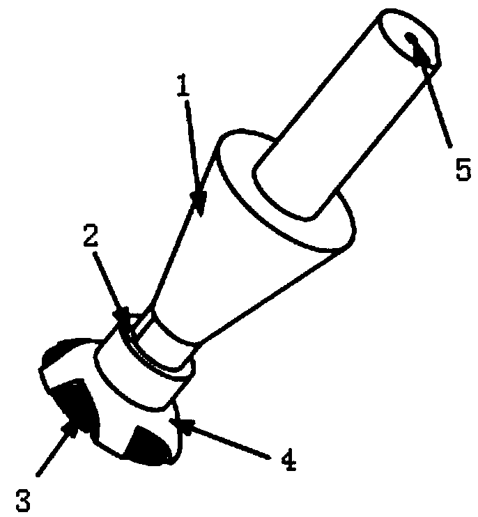
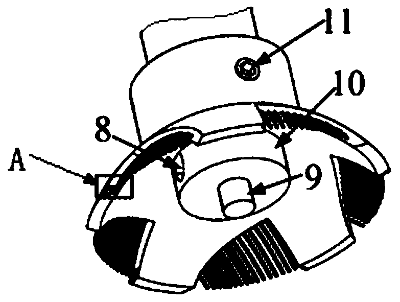
[0040]First determine the type of cooling medium. In this embodiment, the cooling medium is dry ice. According to the cooling medium, select the knife holder 4 without the water outlet 12, and set the knife holder 4 coaxially on the stirring head 1 through the ring connection end of the knife holder 4. , and the circumferential position is defined by the flat key 2, and then the tool holder 4 and the stirring head 1 are fixed by the first top wire 11; the installed stirring head 1 is inserted into the center hole of the main shaft sleeve 14 through the clamping end as a whole , and a sealing gasket is installed between the end face of the conical frustum of the stirring head 1 and the lower end face of the main shaft sleeve 14, and the stirring head 1 and the main shaft sleeve 14 are relatively fixed through the second jacking wire 15 on the main shaft sleeve 14, and the main shaft shaft A sealed bearing 16 is installed in the ho...

Embodiment 2

[0042] Welding of 7075 aluminum alloy sheets.

[0043] In this embodiment, the horizontal compensation method is used for welding, that is, there is a compensation boss at the weld seam, and the height of the boss is 0.2mm; when welding, the pressing amount of the stirring head 1 is 0.2mm from the upper surface of the boss, so as to realize welding without thinning , the inclination angle of the main shaft is 2.5°; the distance between the lower end surface of the tool holder 4 hemispherical end and the end surface of the shaft shoulder 10 of the stirring head 1 is 0.2mm, and the angle α between the end surface of the tool holder 4 hemispherical end and the horizontal plane is 2.5°; other The part is the same as that of Embodiment 1; friction stir welding without burr and thinning is realized while chilling with welding.

Embodiment 3

[0045] Welding of 1060 aluminum alloy.

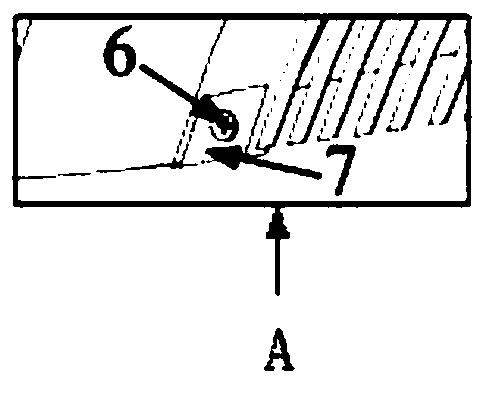
[0046] In this embodiment, when welding, the downward pressure of the stirring head 1 is 0.1 mm, the inclination angle of the main shaft is 2.5°, and the angle α between the hemispherical end surface of the tool holder 4 and the horizontal plane is 2.5°; in this embodiment, due to the 1060 aluminum The alloy material is relatively soft, and the flash is removed in the form of no blade; the milling cutter mounting screw 6 and the milling blade 7 are removed. Others are the same as in Embodiment 1.


PUM

PropertyMeasurementUnit
heightaaaaaaaaaa

Abstract

A friction stir welding stirring tool system capable of achieving trailing intensive cooling and flash removing comprises a knife rest. The knife rest is composed of a circular connecting end and a hemispherical end, and the circular connecting end and the hemispherical end are of an integrally-formed structure. The knife rest is coaxially arranged at the work end of a stirring head in a sleevingmanner through the circular connecting end. Radial rotation of the stirring head and the knife rest is limited through a flat key, and the stirring head and the knife rest are fixed through a first jackscrew. An axial cooling hole is machined in the axis direction of the stirring head. A radial cooling hole communicating with the axial cooling hole is machined in a shaft shoulder of the stirring head in the radial direction. A stirring needle is mounted on the end face of the shaft shoulder of the stirring head. Grooves are evenly formed at the hemispherical end of the knife rest in the circumferential direction, a milling cutter is mounted on the edge of one end face of each groove, and bristles are evenly arranged on the other end face of each groove. By means of the system, the sizes offlashes can be greatly reduced, and the bearing capacity of a weld seam is also improved; and a cooling medium in the stirring head enters from the axial cooling hole of the stirring head through gravity and inflation pressure, manufacturing precision is greatly reduced, and cost is saved.

Description

technical field [0001] The invention belongs to the technical field of a friction stir welding system for removing flash, and in particular relates to a stirring tool system for friction stir welding that is chilled with welding and removes flash. [0002] technical background [0003] Friction stir welding is an advanced welding method widely used in aerospace, electrical and electronic and shipbuilding industries. During the welding process, the stirring head rotates down into the sheet to be welded and moves along the weld seam. The relative movement between the stirring head and the plate generates frictional heat to soften the material, and at the same time, the stirring head exerts a certain upsetting force to make the material flow fully, and the excess material is squeezed out of the weld seam and generates flash. The existence of burrs will not only affect the aesthetics of the welded joints, so other measures are routinely used to remove burrs after welding. At th...

Claims


Application Information

Patent Timeline
Patent Type & Authority Applications(China)
IPC IPC(8): B23P23/04B23K20/12B23K20/26
CPCB23K20/1255B23K20/26B23P23/04
Inventor 岳玉梅任赵旭姬书得温琦马琳宫雪吕赞张利国龚鹏
Owner SHENYANG AEROSPACE UNIVERSITY
Why Eureka
Try Eureka